4
Hooking Up
the
Components
This chapter describes how to connect
various audio and video components
to the receiver. Be sure to read the
sections for the components you have
before you actually connect them to
the receiver.
Unpacking
Check that you received the following items with the
remote:
• FM wire antenna (1)
• AM loop antenna (1)
Models of area code U, CA only
• Audio/video/control S connecting cord (1)
• Control S connecting cord (1)
STR-DB940 only
• Remote commander RM-LJ304 (remote) (1)
• R6 (size-AA) batteries (3)
STR-DB840 only
• Models of area code CED only
– Remote commander RM-PP404 (remote) (1)
– R6 (size-AA) batteries (2)
• Models of other area codes
– Remote commander RM-LP204 (remote) (1)
– R6 (size-AA) batteries (3)
Inserting batteries into the remote
Insert batteries with the + and – properly oriented in the
battery compartment. When using the remote, point it at
the remote sensor
on the receiver.
For details, refer to the operating instructions supplied
with your remote.
z
When to replace batteries
Under normal conditions, the batteries should last for about
3 months (alkaline batteries) or 2 months (manganese batteries).
When the remote no longer operates the receiver, replace all
batteries with new ones.
Notes
• Do not leave the remote in an extremely hot or humid place.
• Do not use a new battery with an old one.
• Do not expose the remote sensor to direct sunlight or lighting
apparatuses. Doing so may cause a malfunction.
• If you don’t use the remote for an extended period of time,
remove the batteries to avoid possible damage from battery
leakage and corrosion.
• This remote is designed for use with alkaline batteries only. Do
not use a combination of different battery types.
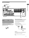
Before you get started
• Turn off the power to all components before making
any connections.
• Do not connect the AC power cord until all of the
connections are completed.
• Be sure to make connections firmly to avoid hum and
noise.
• When connecting an audio/video cord, be sure to
match the color-coded pins to the appropriate jacks on
the components: yellow (video) to yellow; white (left,
audio) to white; and red (right, audio) to red.


