


Getting StartedGetting Started
5
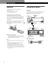
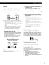
Hookups
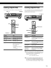
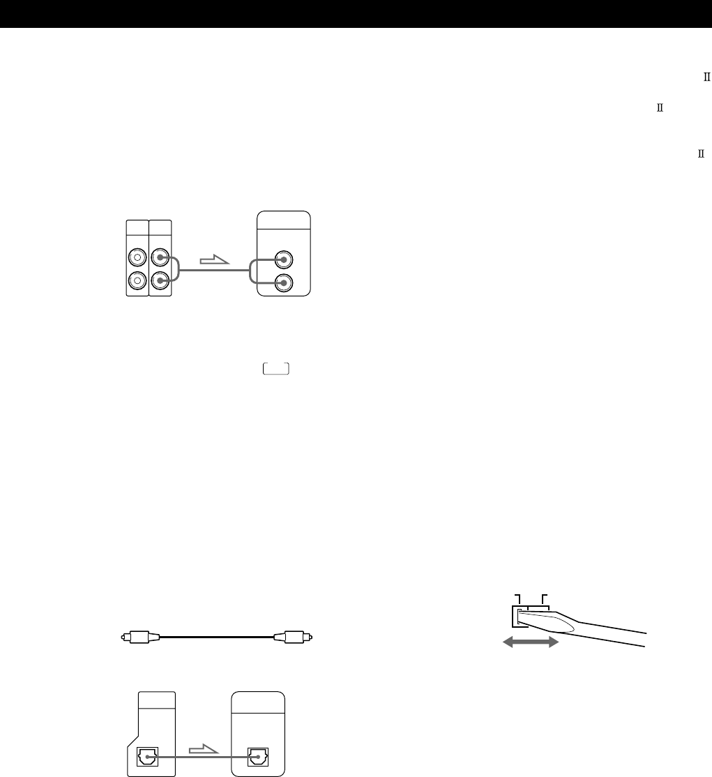
When connecting an audio cord, be sure to match the
color-coded cord to the appropriate jacks on the
components: Red (right) to Red and White (left) to
White. Be sure to make connections firmly to avoid
hum and noise.
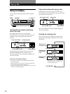
z You can adjust the output level to the amplifier Z
Press ANALOG OUT LEVEL +/– on the remote. You can
reduce the output level up to –20 dB.
When you reduce the output level, “
FADE
” appears in the
display.
Note
If you press the ANALOG OUT LEVEL +/– buttons on
the remote while recording, the recording level will
change even when it is preset on the tape deck, etc.
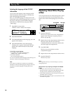
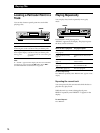
• If you have a digital component such as a digital
amplifier, D/A converter, DAT or MD
Connect the component via the DIGITAL OUT (OPTICAL)
connector using the optical cable (not supplied). Take off
the cap and plug in the optical cable.
Note that you cannot use fading in or out (page 22) and
Time Fade (page 23) functions when making this
connection.
z If you have a Sony component with the CONTROL A1
(or CONTROL A1) jack
Connect the component via the CONTROL A1 (or
CONTROL A1) jack. You can simplify the operation of
audio systems composed of separate Sony components.
For details, refer to the supplementary “CONTROL A1
Control System” instructions.
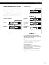
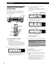
z When using another Sony CD player in conjunction
with this player Z
You can set the supplied remote to be effective on this
player only.
• If the other player’s command mode can be set:
Set the CD1/2/3 switch of this player’s remote to CD1
(factory setting), and set the other player’s remote to
CD2 or CD3.
• If the other player’s command mode cannot be set:
Set the CD1/2/3 switch of this player’s remote to CD2
or CD3.
If you connect this player with another Sony CD
player, you have to set the command mode of each
player. For details, see “Connecting Another CD
Player” on page 6.
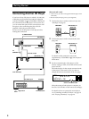
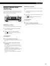
Setting the voltage selector (voltage
selector equipped models only)
Check that the voltage selector on the rear panel of the
player is set to the local power line voltage. If not, set
the selector to the correct position using a screwdriver
before connecting the AC power cord to a wall outlet.
Connecting the AC power cord
Connect the AC power cord to a wall outlet.
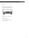
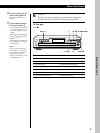
Transporting the player
Before transporting the player, follow the procedure
below to return the internal mechanisms back to their
original position.
1 Remove all the discs from the disc tray.
2 Press A OPEN/CLOSE to close the disc tray.
“–NO DISC–” appears in the display.
3 Wait for 10 seconds, then press POWER to turn off
the player.
AmplifierCD player
POC-15
Optical cable (not supplied)
Note
When you connect via the DIGITAL OUT (OPTICAL)
connector, noise may occur when you play CD software other
than music, such as a CD-ROM.
CD player Digital component
ANALOG
IN OUT
L
R
INPUT
CD
L
R
2ND
CD
DIGITAL
INPUT
OPTICAL
DIGITAL
OUT
OPTICAL
110 - 120 V220 - 240 V