


– 13 –
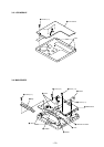
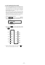
IC502
FB501
C530
25
26
28
32
36
1
47
118
116
119
120
117
114113 112
115
110109 111
104108 106
104105 103
101102 100
144 146
37 46 47 50 53 5659 64 68
42 45 48 51 55 5760 63 66 67
145
88
88 87 86 83 81 78 7472 69 64 63 60 58
90 89 85 84 80 77 7571 68 65 62 59 57
93 92 91
96 95 94
99 98 97
82 79 76 73 70 67 66 6155 56
52 53 54
49 50 51
46 47 48
43 45 44
40 41 42
37 36 39
34 35 36
32 33
26 28 31
25 29 30
19 22 27
21 23
20 24
10 1316
11 1417
12 1518
74
268
1359
85
82
78
76
73
89
86
83
80
90
87
84
81
77
74
72
79
75
43 44 49 52 54 5861 62 65 69
70
71
38 40
39 41
AP508
AP504
AP505
R530
R529
C529
S804
HOLD
AP1001
L502
FB503FB502
FB504
BP801
AP519
AP830
AP521
OFF ON
R506
R503
R508
R509
R510
C537
R935
AP5209
AP806
C801
AP911
AP807
AP907
AP834
AP517
X801
AP511
AP516
1
2
0
9
AP506
1
0
3
2
AP804
AP803
AP507
8
05
IC802
IC801
8
1
54
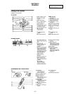
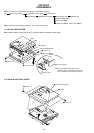
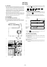
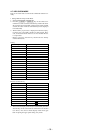
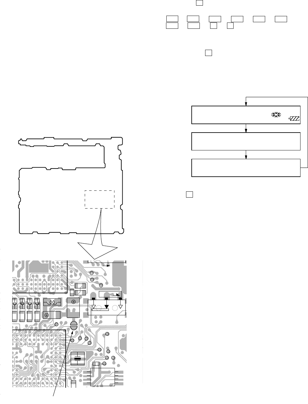
– MAIN BOARD (SIDE B) –
BP801
SECTION 4
TEST MODE
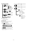
4-1. OUTLINE
• This set provides the Overall adjustment mode (Assy mode) that
allows CD and MO disc to be automatically adjusted when in
the test mode. In this overall adjustment mode, the protect switch
is detected to judge the disc, CD or MO, and each adjustment is
automatically executed in order. If a fault is found, the system
displays its location. Also, the manual mode allows each indi-
vidual adjustment to be automatically adjusted.
• The keys in the description refer to the keys on both set and
remote commander unless otherwise specified. Though LCD
display shows the LCD of the remote commander, same con-
tents are also displayed on the LCD of the set.
4-2. TEST MODE
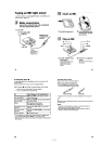
4-2-1. Setting Method of Test Mode
There are two different methods to set the test mode:
1 Short BP801 (TEST) on the MAIN board with a solder bridge
(connect pin y; of IC801 to the ground). Then, turn on the
power.
2 In the normal mode, turn on the HOLD switch on the set. While
pressing the
x key on the set, press the following remote
control keys in the following order:
> t > t . t . t > t . t
> t . t X t X
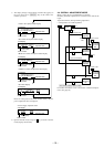
4-2-2. Operation in Setting the Test Mode
• When the test mode becomes active, first the display check mode
is selected. (Press
x key once, when the display check mode
is not active.)
• Other mode can be selected from the display check mode.
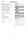
• When the test mode is set, the LCD repeats the following dis-
play.
LCD display
• When the
X key is pressed and hold down, the display at that
time is held so that display can be checked.
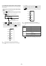
4-2-3. Releasing the Test Mode
For test mode set with the method 1:
Turn off the power and open the solder bridge on BP801 (TEST)
on the MAIN board.
Note:Remove the solders completely. Remaining could be shorted with
the chassis, etc.
For test mode set with the method 2:
Turn off the power.
Note: If electrical adjustment (see page 20) has not been finished com-
pletely, always start in the test mode. (The set cannot start in nor-
mal mode.)
Microprocessor
version
display
All off
All lit
xxxxxxxxx
V0.000
888
001
F1SHUF
REC