


3
1. SERVICING NOTE......................................................... 4
2. GENERAL
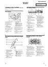
Looking at the Controls (MZ-G750)................................... 5
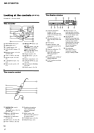
Looking at the Controls (MZ-R700) ................................... 6
3. DISASSEMBLY
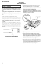
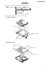
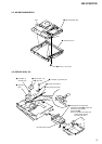
3-1. Panel Assy, Lower............................................................... 7
3-2. Panel Assy, Upper ............................................................... 7
3-3. LCD Module ....................................................................... 8
3-4. Main Board ......................................................................... 8
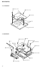
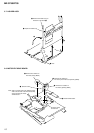
3-5. MD Mechanism Deck ......................................................... 9
3-6. Service Assy, OP ................................................................. 9
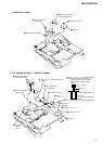
3-7. Holder Assy....................................................................... 10
3-8. Motor Flexible Board ........................................................ 10
3-9. Motor, DC (M602) ............................................................ 11
3-10. “Motor, DC (M601)”, “Motor, DC (M603)” .................... 11
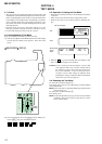
4. TEST MODE
4-1. Outline ............................................................................... 12
4-2. Setting Method of Test Mode ............................................ 12
4-3. Operation in Setting the Test Mode................................... 12
4-4. Releasing the Test Mode ...................................................12
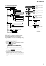
4-5. Configuration of Test Mode .............................................. 13
4-6. Manual Mode .................................................................... 13
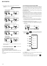
4-7. Overall Adjustment Mode ................................................. 14
4-8. Self-Diagnosis Result Display Mode ................................ 14
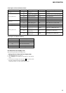
4-9. Result the Error Display Code .......................................... 15
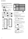
4-10. Sound Skip Check Result Display Mode .......................... 16
4-11. Key Check Mode ............................................................... 16
TABLE OF CONTENTS
5. ELECTRICAL ADJUSTMENTS
5-1. Outline ............................................................................... 18
5-2. Precautions for Adjustment ............................................... 18
5-3. Adjustment Sequence ........................................................ 18
5-4. NV Reset ........................................................................... 18
5-5. Power Supply Manual Adjustment.................................... 19
5-6. Temperature Correction..................................................... 20
5-7. Laser Power Check ........................................................... 20
5-8. Overall Adjustment Mode ................................................. 21
5-9. Resume Clear .................................................................... 23
5-10. Patch Data Rewriting when Nonvolatile
Memory was Replaced...................................................... 23
6. DIAGRAMS
6-1. IC Pin Function Description ............................................ 29
6-2. Block Diagram – Servo Section – ..................................... 35
6-3. Block Diagram – Audio Section – .................................... 36
6-4. Block Diagram – System Control/Power Section – .......... 37
6-5. Printed Wiring Board – Main Section – ............................ 38
6-6. Schematic Diagram – Main Section (1/3) – ...................... 41
6-7. Schematic Diagram – Main Section (2/3) – ...................... 42
6-8. Schematic Diagram – Main Section (3/3) – ...................... 43
7. EXPLODED VIEWS
7-1. Panel Section..................................................................... 47
7-2. Chassis Section ................................................................. 48
7-3. MD Mechanism Deck Section .......................................... 49
8. ELECTRICAL PARTS LIST ...................................... 50
MZ-G750/R700