


12
MZ-G750/R700
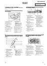
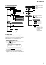
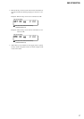
2 In the normal mode, turn on the [HOLD] switch. While press-
ing the [VOL --] key press the following order:
> t > t . t . t > t
. t > t . t X t X
SECTION 4
TEST MODE
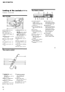
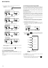
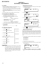
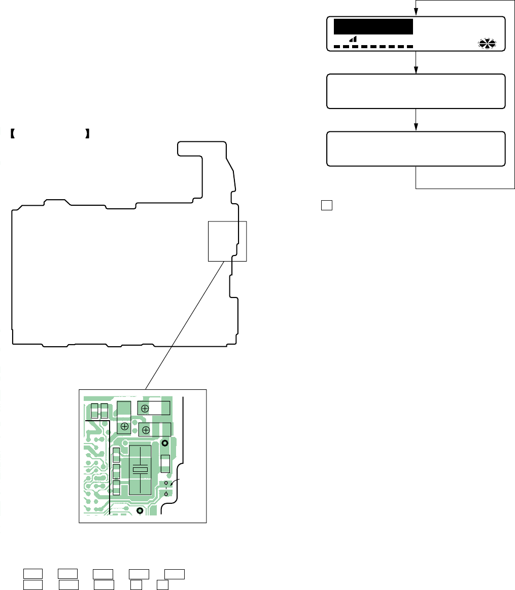
4-3. Operation in Setting the Test Mode
• When the test mode becomes active, first the display check mode
is selected.
• Other mode can be selected from the display check mode.
• When the test mode is set, the LCD repeats the following dis-
play.
• When the
X key is pressed and hold down, the display at that
time is held so that display can be checked.
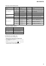
Caution: On the set having the microcomputer version 1.000,
some adjusted values were set in the manual mode at
the shipment, but these data will be cleared when the
NV is reset. Therefore, on the set having the micro-
computer version 1.000, change the adjusted values
following the Change of Adjusted Values immediately
after the NV was reset (see page 18).
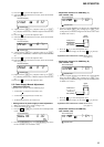
4-4. Releasing the Test Mode
For test mode set with the method 1:
Turn off the power and open the solder bridge on SL801 (TEST)
on the MAIN board.
Note: Remove the solders completely. Remaining could be shorted
with the chassis, etc.
For test mode set with the method 2:
Turn off the power.
Note: If electrical adjustment (see page 18) has not been finished
completely, always start in the test mode. (The set cannot
start in normal mode)
4-1. Outline
• This set provides the Overall adjustment mode that allows CD
and MO discs to be automatically adjusted when in the test mode.
In this overall adjustment mode, the disc is discriminate between
CD and MO, and each adjustment is automatically executed in
order. If a fault is found, the system displays its location. Also,
the manual mode allows each individual adjustment to be auto-
matically adjusted.
• Operation in the test mode is performed with the set. A key
having no particular description in the text, indicates a set key.
• For the LCD display, the LCD on the set is shown.
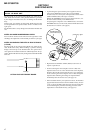
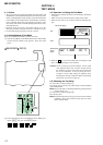
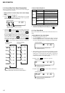
4-2. Setting Method of Test Mode
There are two different methods to set the test mode:
1 Short SL801 (TEST) on the MAIN board with a solder bridge
(connect pin 3 of IC801 to the ground). Then, turn on the
power.
MAIN BOARD (SIDE B)
C821
C815
X801
SL801
(TEST)
C809
R817
C807C808R806
C814
FB801
AP817
AP828
BASS
All lit
This set LCD display
SYNCMONOLP24 REC
REC DATE REMAIN
1 SHUFF PGM
AM
PM
F
e
88:88
00 5
All off
Microcomputer
version
display
Ver 1.200