


– 15 – – 16 –
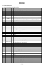
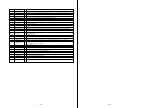
Pin No. Pin Name I/O Description
50 CLV W CON I Spindle servo (W) drive signal input from the BD6602KUT (IC551)
51 DRV VCON O Driver output control terminal to the DB6602KUT (IC551) “L”: prohibited, “H”: permission
52 NC — Not used. (open)
53 SLED 1R CON O Sled motor control signal output to the BD6602KUT (IC551)
54 SLED 1F CON O Sled motor control signal output to the BD6602KUT (IC551)
55 SLED 2R CON O Sled motor control signal output to the BD6602KUT (IC551)
56 SLED 2F CON O Sled motor control signal output to the BD6602KUT (IC551)
57 – 60 NC — Not used. (open)
61 VSS — Ground terminal (digital system)
62 NC — Not used. (open)
63 RMC DTCK I/O TSB serial communication data input/output terminal for remote commander with headphone
64 S0 O PD-IC mode select signal output
65 S1 O PD-IC mode select signal output
66, 67 NC — Not used. (open)
68 SLD VCON O Sled servo control PWM signal output to the BD6602KUT (IC551)
69 NC — Not used. (open)
70 HP MUTE O Muting on/off control signal output to the headphone amplifier (IC301) “H”: muting on
71 HP STBY O
Standby on/off control signal output to the headphone amplifier (IC301)
“L”: standby mode, “H”: amplifier on
72 NC — Not used. (open)
73 NV DI I Serial data input from the EEPROM (IC802)
74 NV DO O Serial data output from the EEPROM (IC802)
75 NV CLK O Serial clock signal output to the EEPROM (IC802)
76 NV CS1 O Chip select signal output to the EEPROM (IC802)
77 ADJUST I Test mode institution input terminal “L”: test mode (Normally, fixed at “H”)
78 XREBOOT O System reboot control output terminal
79 VDD — Power supply terminal (+2 V) (digital system)
80 VSS — Ground terminal (digital system)