


2
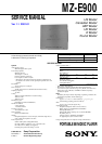
MZ-E900
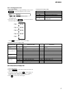
Specifications ........................................................................... 1
1. SERVICING NOTE ...................................................... 2
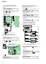
2. GENERAL
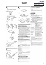
Location and Function of Controls .................................... 3
3. DISASSEMBLY
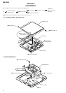
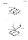
3-1. “Lid ASSY, Upper”, Holder ASSY ............................ 4
3-2. Mechanism Deck ........................................................ 4
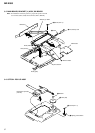
3-3. Audio Board................................................................ 5
3-4. Bracket (L) ASSY, Bracket (R) ASSY ....................... 5
3-5. Main Board, Bracket (L) ASSY, SW Board ............... 6
3-6. Optical Pick-up ASSY ................................................ 6
4. TEST MODE.................................................................. 7
5. ELECTRICAL ADJUSTMENTS............................11
6. DIAGRAMS
6-1. Block Diagram.......................................................... 15
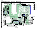
6-2. Printed Wiring Boards – Main Section (1/2) – ......... 16
6-3. Printed Wiring Boards – Main Section (2/2) – ......... 17
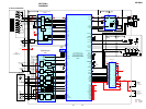
6-4. Schematic Diagram – Main Section (1/2) – ............. 18
6-5. Schematic Diagram – Main Section (2/2) – ............. 19
6-6. Printed Wiring Boards – Audio Section – ................ 20
6-7. Schematic Diagram – Audio Section – ..................... 21
7. EXPLODED VIEWS
7-1. Front Section ............................................................ 25
7-2. Mechanism Deck Section ......................................... 26
8. ELECTRICAL PARTS LIST ................................... 27
SAFETY-RELATED COMPONENT WARNING!!
COMPONENTS IDENTIFIED BY MARK ! OR DOTTED LINE WITH
MARK !ON THE SCHEMATIC DIAGRAMS AND IN THE PARTS
LIST ARE CRITICAL TO SAFE OPERATION.
REPLACE THESE COMPONENTS WITH SONY PARTS WHOSE
PART NUMBERS APPEAR AS SHOWN IN THIS MANUAL OR IN
SUPPLEMENTS PUBLISHED BY SONY.
Flexible Circuit Board Repairing
• Keep the temperature of the soldering iron around 270°C during
repairing.
• Do not touch the soldering iron on the same conductor of the
circuit board (within 3 times).
• Be careful not to apply force on the conductor when soldering or
unsoldering.
Notes on chip component replacement
• Never reuse a disconnected chip component.
• Notice that the minus side of a tantalum capacitor may be dam-
aged by heat.
TABLE OF CONTENTS
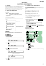
SECTION 1
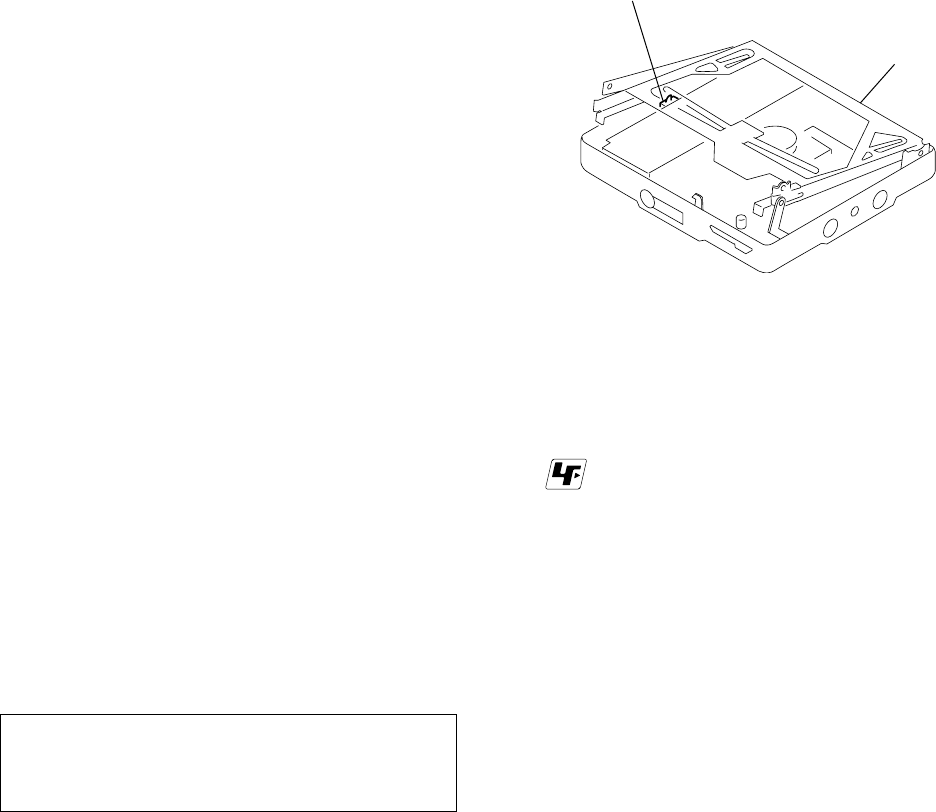
SERVICING NOTE
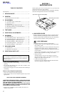
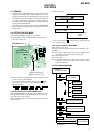
When repairing this device with the power on, if you remove the
main board, this device stops working.
In this case, you work without the device stopping by fastening
the hook of the Open/Close detection switch (S809).
* Replacement of CXD2671-201GA (IC601) used in this set
requires a special tool.
CAUTION
Use of controls or adjustments or performance of procedures
other than those specified herein may result in hazardous
radiation exposure.
Open/Close detection switch (S809)
Mechanism deck sectio
n
r
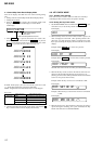
UNLEADED SOLDER
Boards requiring use of unleaded solder are printed with the
lead-free mark (LF) indicating the solder contains no lead.
(Caution: Some printed circuit boards may not come printed
with the lead free mark due to their particular size.)
: LEAD FREE MARK
Unleaded solder has the following characteristics.
• Unleaded solder melts at a temperature about 40°C higher
than ordinary solder.
Ordinary soldering irons can be used but the iron tip has to
be applied to the solder joint for a slightly longer time.
Soldering irons using a temperature regulator should be set
to about 350°C.
Caution: The printed pattern (copper foil) may peel away if
the heated tip is applied for too long, so be careful!
• Strong viscosity
Unleaded solder is more viscous (sticky, less prone to
flow) than ordinary solder so use caution not to let solder
bridges occur such as on IC pins, etc.
• Usable with ordinary solder
It is best to use only unleaded solder but unleaded solder
may also be added to ordinary solder.
Ver 1.1 2001.01