


47
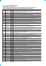
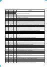
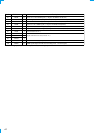
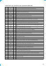
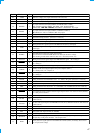
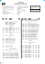
Pin No. Pin Name I/O Description
43 AVRH
I Reference voltage (+5V) input terminal (for A/D converter)
44 AVRL
I Reference voltage (0V) input terminal (for A/D converter)
45 AVSS
— Ground terminal (for analog system)
46 KEYIN0
I
Key input terminal (A/D input) (LSW901 to LSW908, S901 to S904)
OFF, SOURCE, SOUND, MENU, PTY DSPL, LIST, ENTER, MODE,
SEEK/AMS -
.
m
+
>
M
, DISC/PRST +, PRST/DISC - keys input
47 KEYIN1
I
Key input terminal (A/D input) (LSW810, LSW909 to LSW917)
Z
, D-BASS, TA, AF, 6 to 3 SHUF 2, REP 1 keys input
48 RCIN0
I Rotary remote commander key input terminal (A/D input)
49 DSTSEL I
Destination setting terminal (fixed at “L” in this set)
50 QUALITY
I Noise level detection signal input at SEEK mode (A/D input)
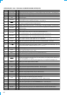
51
FMAGC I
FM AGC detection signal input from the FM/AM tuner unit (TU1) (A/D input)
52 MPTH
I Multi-path detection signal input from the RDS decoder (IC51) (A/D input)
53
VSM I
FM and AM signal meter voltage detection input from the FM/AM tuner unit (TU1)
(A/D input)
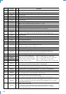
54 VCC —
Power supply terminal (+5V)
55 RAMBU I
Internal RAM reset detection signal input terminal
Input terminal to check that RAM data are not destroyed due to low voltage
This checking is made within 100 msec after reset Not used (fixed at “H”)
56 TUNATT O
Muting on/off control signal output of the FM/AM tuner signal “H”: muting on
57 VOLATT
O
Pre amplifier muting on/off control signal output to the electrical volume (IC151)
“L”: muting on
58 ATT
O Audio line muting on/off control signal output terminal “H”: muting on
59 AMPON
O
Standby on/off control signal output to the power amplifier (IC611)
“L”: standby mode, “H”: ampifier on
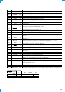
60 AMPATT
O
Power amplifier muting on/off control signal output to the power amplifier (IC611)
“L”: muting on
61 COLSW
I Setting terminal for the illumination color “L”: 2 color, “H”: 1 color (fixed at “H” in this set)
62 COLSEL
I Setting terminal for the illumination color “L”: amber, “H”: green (fixed at “L” in this set)
63 VSS —
Ground terminal
64 DAVN I
Data transmit completed detection signal input from the RDS decoder (IC51) “H” active
65 FILE
I Setting terminal for the custom file “L”: unavailable, “H”: available (fixed at “H” in this set)
66 TEXT
I Setting terminal for the CD text “L”: unavailable, “H”: available (fixed at “H” in this set)
67 NOSESW I
Front panel block remove/attach detection signal input from the nose detection switch (SW504)
“L”: front panel is attached
68, 69 NCO O
Not used (open)
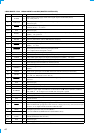
70 I2C SIO I/O
Two-way data I2C bus with the FM/AM tuner unit (TU1), RDS decoder (IC51) and electrical
volume (IC151)
71 I2C CKO O
I2C bus clock signal output to the FM/AM tuner unit (TU1), RDS decoder (IC51) and electrical
volume (IC151)
72 NCO O
Not used (open)
73 X1A O
Sub system clock output terminal (32.768 kHz)
74 X0A I
Sub system clock input terminal (32.768 kHz)
75 NCO O
Not used (open)
76 KEYACK
I
Input of acknowledge signal for the key entry Acknowledge signal is input to accept function
and eject keys in the power off status On at input of “H”
77 BUIN
I
Battery detection signal input from the SONY bus interface (IC701) and battery detect circuit
“L” is input at low voltage