


26
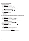
6. Press the = , + buttons so that the reading of the laser
power meter becomes 6.9 to 7.1 mW, press the ^ “PRO-
GRAM” button and save it.
Note : Do not perform the emission with 7.0 mW more than 15
seconds continuously.
7. Then, press the + button and display “PWR CHECK”.
8. Press the ^ “PROGRAM” button once and display “0.9
mW*** $ ”. Check that the reading of the laser power meter
become 0.85 to 0.91 mW. (*** means IOP value)
9. Press the ^ “PROGRAM” button once more and display
“7.0 mW*** $ ”. Check that the reading the laser power meter
and digital volt meter satisfy the specified value.
Note down the digital voltmeter reading value.
Specified Value :
Laser power meter reading : 7.0 ± 0.1 mW
Digital voltmeter reading : Optical pick-up displayed value ± 10%
(Optical pick-up label)
10. Press the p “PROGRAM” button and display “LDPWR
CHECK” and stop the laser emission.
(The p “PROGRAM” button is effective at all times to stop
the laser emission.)
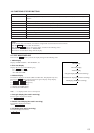
11. Press the + button to display “Iop.Write”.
12. Press the ^ “PROGRAM” button. When the display be-
comes Ref=@@@.@ (@ is an arbitrary number), press the ^
“PROGRAM” button to display “Measu=@@@.@” (@ is an
arbitrary number).
13. The numbers which can be changed will blink. Input the Iop
value noted down at step 9.
To select the number : Press the = , + buttons.
To select the digit : Press the r “PROGRAM” buttan
14. When the ^ “PROGRAM” button is pressed, “Complete!”
will be displayed momentarily. The value will be recorded in
the non-volatile memory and the display will become “Iop
Write”.
Note 1: After step 4, each time the ^ “PROGRAM” button is
pressed, the display will be switched between “0.7 mW***
$ ”, “6.2 mW*** $ ”, and “ WP *** $ ”.
Nothing needs to be performed here.
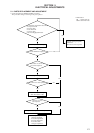
5-11. TRAVERSE ADJUSTMENT
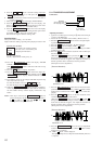
Connection :
Adjusting Procedure :
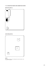
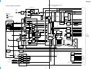
1. Connect an oscilloscope to CN110 pin 3 (TE) and CN110 pin
1 (VC) of the BD board.
2. Load a disc (any available on the market). (Refer to Note 1.)
3. Press the + “PROGRAM” button and move the optical pick-
up outside the pit.
4. Press the + button and display “EF MO ADJUST”.
5. Press the + button and display “EFB =
MO-R”.
(Laser power READ power/Focus servo ON/tracking servo OFF/
spindle (S) servo ON)
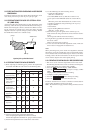
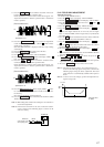
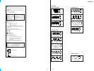
6. Press the + button so that the waveform of the oscilloscope
becomes the specified value.
(When the = , + buttons is pressed, the of “EFB= ”
changes and the waveform changes.) In this adjustment, wave-
form varies at intervals of approx. 2%. Adjust the waveform so
that the specified value is satisfied as much as possible.
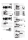
(Read power traverse adjustment)
(Traverse Waveform)
7. Press the ^ “PROGRAM” button and save the result of ad-
justment to the non-volatile memory (“EFB = SAVE” will be
displayed for a moment. Then “EFB = MO-W” will be dis-
played).
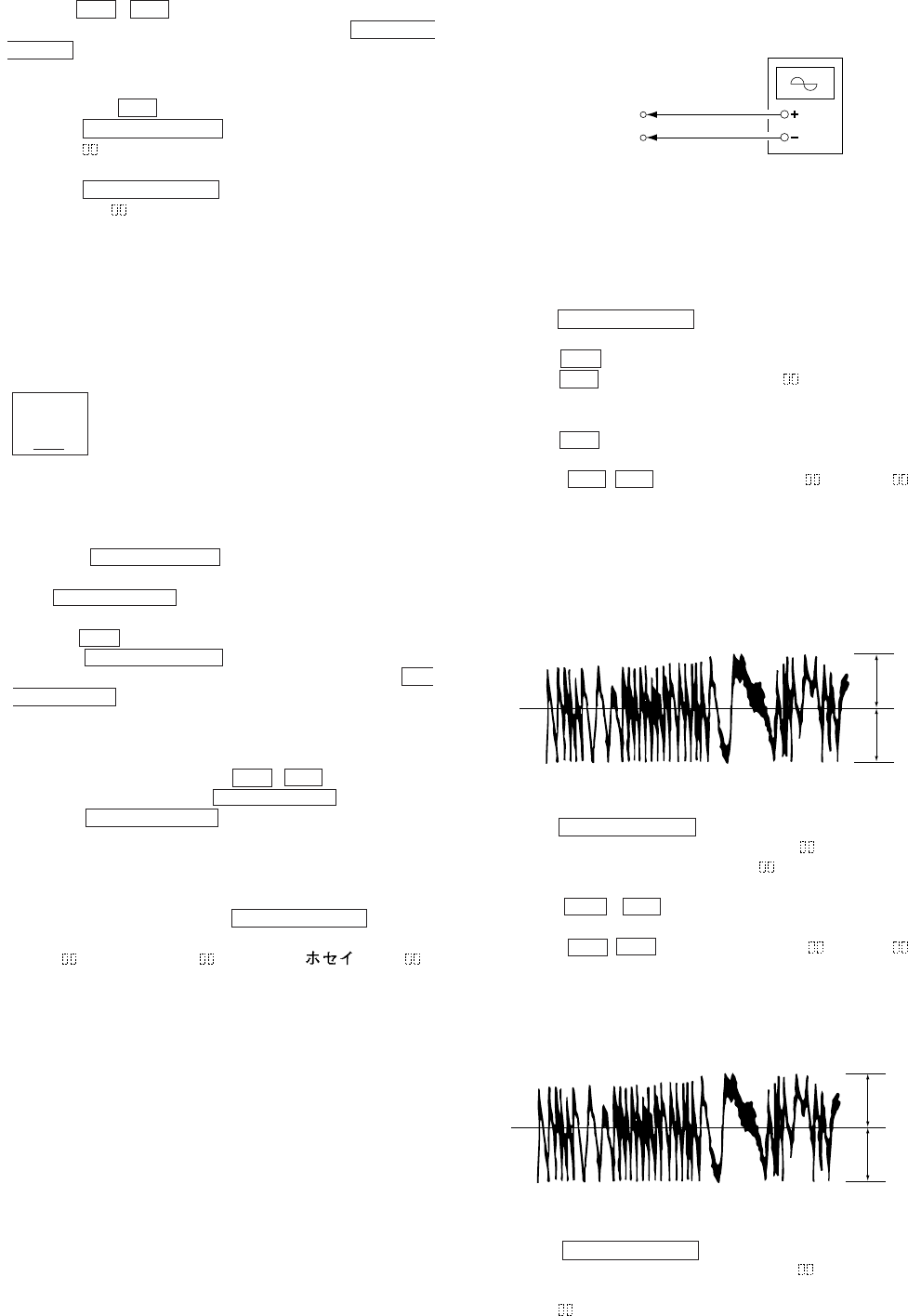
8. Press the = , + buttons so that the waveform of the
oscilloscope becomes the specified value.
(When the = , + buttons is pressed, the of “EFB- ”
changes and the waveform changes.) In this adjustment, wave-
form varies at intervals of approx. 2%. Adjust the waveform so
that the specified value is satisfied as much as possible.
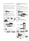
(Write power traverse adjustment)
(Traverse Waveform)
9. Press the ^ “PROGRAM” button, and save the adjustment
results in the non-volatile memory. (“EFB =
SAVE” will be
displayed for a moment.)
10. “EFB = MO-P”. will be displayed.
The optical pick-up moves to the pit area automatically and servo
is imposed.
V : 0.5 V/div
H : 10 ms/div
Input : DC mod
e
Oscilloscope
BD board
CN110 pin
3
(TE)
CN110 pin
1
(VC)
VC
A
B
Specification A = B
VC
A
B
Specification A = B
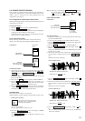
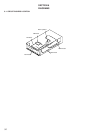
KMS
260A
27X40
B0825
N
Iop = 82.5 mA in this case
Iop (mA) = Digital voltmeter reading (mV)/1 (
Ω
)
(For details of the method for checking
this value, refer to “5-8. Recording and
Displaying IOP Information”.)