


19
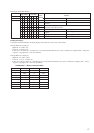
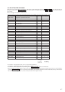
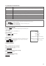
4-6. FUNCTIONS OF OTHER BUTTONS
Contents
Sets continuous playback when pressed in the STOP state. When pressed during continuous playback, the tracking servo turns
ON/OFF.
Stops continuous playback and continuous recording.
The sled moves to the outer circumference only when this is pressed.
The sled moves to the inner circumference only when this is pressed.
Switches between the pit and groove modes when pressed.
Switches the spindle servo mode (CLV S ˜ CLV A).
Switches the displayed contents each time the button is pressed
Ejects the disc
Exits the test mode
Function
^
p
+ “PROGRAM” *
= “PROGRAM” *
r “1” *
^ “1” *
p “1”
6 (EJECT)
6 “1” *
*Note:
As this unit has only a few buttons, one button is assigned with several functions in the test mode.”
Press the INPUT button to switch the functions.
Each time the INPUT button is pressed, the display switches in the following order;”
“PROGRAM” n “1” n blank n “PROGRAM”
The functions of each button change with the display.
Mode display
Error rate display
Address display
Auto gain display (Not used in servicing)
Detrack check display (Not used in servicing)
IVR display (Not used in servicing)
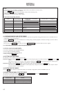
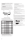
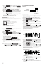
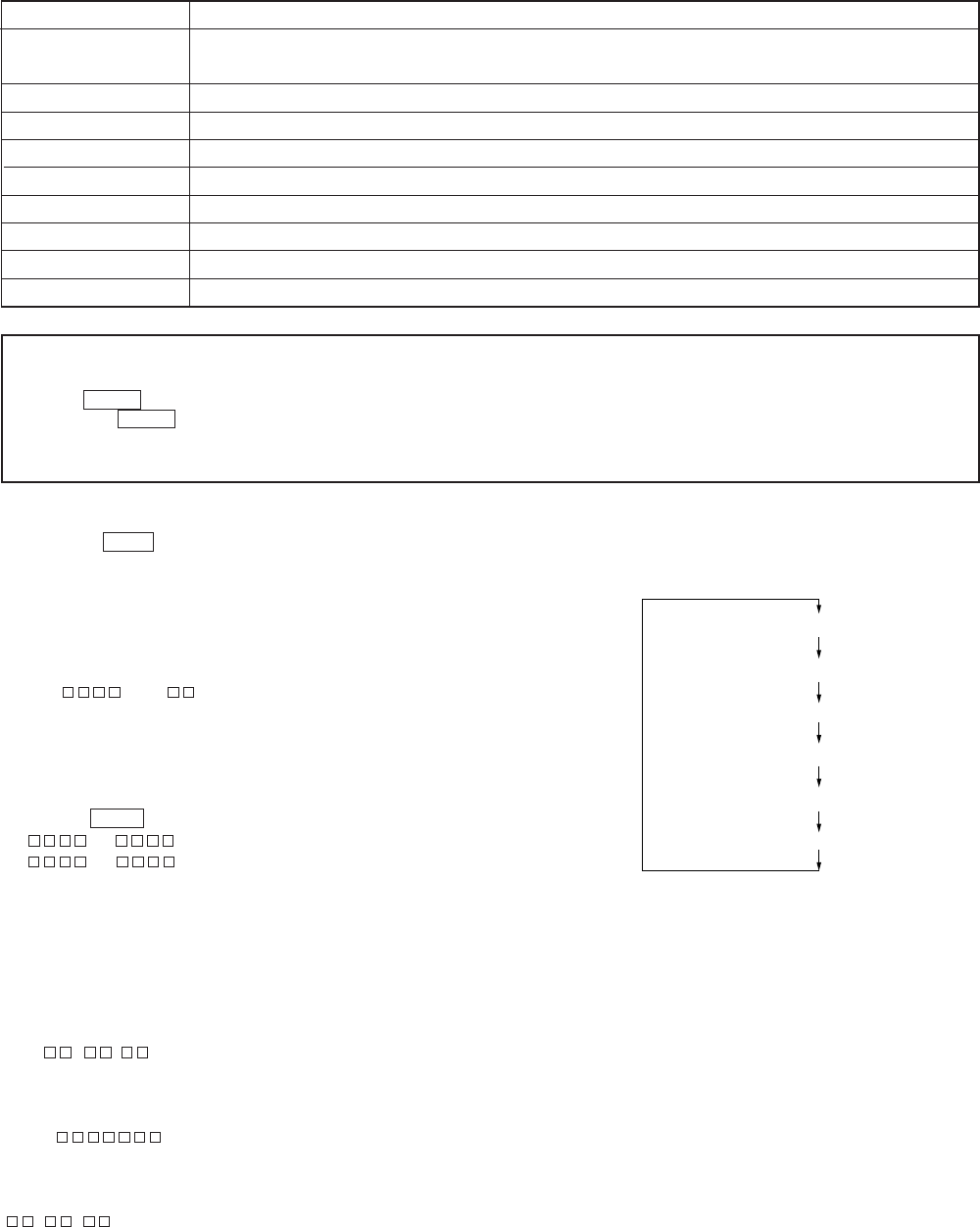
4-7. TEST MODE DISPLAYS
Each time the p “1” button is pressed, the display changes in the following order.
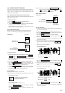
1. Mode display
Displays “TEMP ADJUST”, “CPLAYMODE”, etc.
2. Error rate display
Displays the error rate in the following way.
C1 = AD =
C1 = Indicates the C1 error.
AD = Indicates ADER.
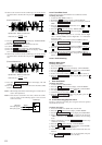
3. Address display
The address is displayed as follows. (MO:recordable disc, CD:playback only disc)
Pressing the r “1” button switches between the groove display and pit display.
h = s = (MO pit and CD)
h = a = (MO groove)
h = Indicates the header address.
s = Indicates the SUBQ address.
a = Indicates the ADIP address.
Note : “–” is displayed when servo is not imposed.
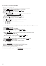
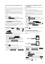
4. Auto gain display (Not used in servicing)
The auto gain is displayed as follows.
AG = / [ ]
5. Detrack check display (Not used in servicing)
The detrack is displayed as follows.
ADR =
6. IVR display (Not used in servicing)
The IVR is displayed as follows.
[ ][ ][