


4
Description
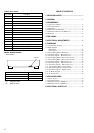
TABLE OF CONTENTS
1. SERVICING NOTES ............................................. 5
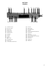
2. GENERAL ........................................................................ 11
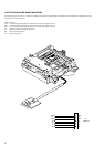
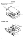
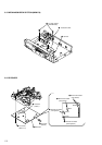
3. DISASSEMBLY
3-1. Upper Case (408226) .......................................................... 12
3-2. Front Panel Section ............................................................. 12
3-3. Main Board ......................................................................... 13
3-4. PT Board, VOL-SEL Board ................................................ 13
3-5. Mechanism Deck Section (MDM-7A)................................ 14
3-6. BD Board ............................................................................ 14
4. TEST MODE ..................................................................... 15
5. ELECTRICAL ADJUSTMENTS ............................... 20
6. DIAGRAMS
6-1. Circuit Boards Location ...................................................... 31
6-2. Block Diagrams
• BD Section .......................................................................32
• Main Section ....................................................................33
6-3. Printed Wiring Board – BD Section –................................. 35
6-4. Schematic Diagram – BD Section (1/2) –........................... 36
6-5. Schematic Diagram – BD Section (2/2) –........................... 37
6-6. Printed Wiring Board – Main Section (Side A) – ............... 38
6-7. Printed Wiring Board – Main Section (Side B) – ............... 39
6-8. Schematic Diagram – Main Section (1/3) –........................ 40
6-9. Schematic Diagram – Main Section (2/3) –........................ 41
6-10. Schematic Diagram – Main Section (1/3) – .....................42
6-11. Printed Wiring Board – Power Section – ......................... 43
6-12. Printed Wiring Board – Display Section – ....................... 44
6-13. Schematic Diagram – Display Section –.......................... 45
6-14. IC Block Diagrams........................................................... 46
6-15. IC Pin Functions............................................................... 48
7. EXPLODED VIEWS
7-1. Chassis Section ................................................................... 54
7-2. Front Panel Section .............................................................55
7-3. Mechanism Section-1 (MDM-7A)...................................... 56
7-4. Mechanism Section-2 (MDM-7A)...................................... 57
8. ELECTRICAL PARTS LIST ........................................ 58
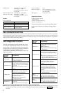
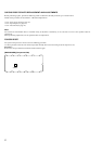
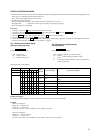
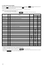
Table of Error Codes
Error Code
10
12
20
21
22
23
24
30
31
40
41
42
43
50
51
Could not load
Loading switches combined incorrectly
Timed out without reading the top of PTOC
Could read top of PTOC, but detected error
Timed out without accessing UTOC
Timed out without reading UTOC
Error in UTOC
Could not start playback
Error in sector
Retry cause generated during normal recording
Retried in DRAM overflow
Retry occurred during TOC writing
Retry aborted during S.F editing
Other than access processing, and could not read address.
Focus NG occurred and overran.
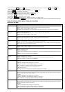
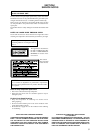
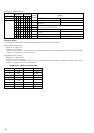
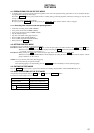
MODEL IDENTIFICATION
— BACK PANEL —
Part No.
• Abbreviation
SP : Singapore model
MY : Malaysia model
MODEL
AEP, UK, CIS models
Canadian model
SP, MY models
PARTS No.
4-228-638-0s
4-228-638-3s
4-228-638-4s