


26
5-7. INITIAL SETTING OF ADJUSTMENT VALUE
Note:
Mode which sets the adjustment results recorded in the non-vola-
tile memory to the initial setting value. However the results of the
temperature compensation offset adjustment will not change to the
initial setting value.
If initial setting is performed, perform all adjustments again ex-
cluding the temperature compensation offset adjustment.
For details of the initial setting, refer to “5-4. Precautions on Ad-
justments” and execute the initial setting before the adjustment as
required.
Setting Procedure :
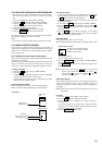
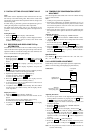
1. Rotate the AMS knob to display “ADJ CLEAR”.
2. Press the YES button. “Complete!” will be displayed momen-
tarily and initial setting will be executed, after which “ADJ
CLEAR” will be displayed.
5-8. RECORDING AND DISPLAYING THE Iop
INFORMATION
The IOP data can be recorded in the non-volatile memory. The Iop
value on the label of the optical pick-up and the Iop value after the
adjustment will be recorded. Recording these data eliminates the
need to read the label on the optical pick-up.
Recording Procedure :
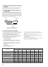
1. While pressing the AMS knob and x button, connect the
power plug to the outlet, and release the AMS knob and x
button.
2. Rotate the AMS knob to display “[Service]”, and press the
YES button.
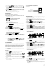
3. Rotate the AMS knob to display “Iop.Write”, and press the
YES button.
4. The display becomes Ref=@@@.@ (@ is an arbitrary number)
and the numbers which can be changed will blink.
5. Input the Iop value written on the optical pick-up.
To select the number : Rotate the AMS knob.
To select the digit : Press the AMS knob
6. When the YES button is pressed, the display becomes
“Measu=@@@.@” (@ is an arbitrary number).
7. As the adjustment results are recorded for the 6 value. Leave it
as it is and press the YES button.
8. “Complete!” will be displayed momentarily. The value will be
recorded in the non-volatile memory and the display will be-
come “Iop Write”.
Display Procedure :
1. Rotate the AMS knob to display “Iop.Read”.
2. “@@.@/##.#” is displayed and the recorded contents are dis-
played.
@@.@ indicates the Iop value labeled on the pick-up.
##.# indicates the Iop value after adjustment
3. To end, press the AMS button or MENU/NO button to display
“Iop Read”.
5-9. TEMPERATURE COMPENSATION OFFSET
ADJUTMENT
Save the temperature data at that time in the non-volatile memory
as 25 ˚C reference data.
Note :
1. Usually, do not perform this adjustment.
2. Perform this adjustment in an ambient temperature of 22 ˚C to
28 ˚C. Perform it immediately after the power is turned on when
the internal temperature of the unit is the same as the ambient
temperature of 22 ˚C to 28 ˚C.
3. When D101 has been replaced, perform this adjustment after
the temperature of this part has become the ambient tempera-
ture.
Adjusting Procedure :
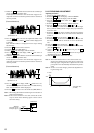
1. Rotate the AMS knob and display “TEMP ADJUST”.
2. Press the YES button and select the “TEMP ADJUST” mode.
3. “TEMP = [OK]” and the current temperature data will be
displayed.
4. To save the data, press the YES button.
When not saving the data, press the MENU/NO button.
5. When the YES button is pressed, “TEMP = SAVE” will be
displayed and turned back to “TEMP ADJUST” display then.
When the MENU/NO button is pressed, “TEMP ADJUST”
will be displayed immediatelly.
Specified Value :
The “TEMP = ” should be within “E0 - EF”, “F0 - FF”, “00 -
0F”, “10 - 1F” and “20 - 2F”.
5-10. LASER POWER ADJUSTMENT
Check the Iop value of the optical pick-up before adjustments.
(Refer to 5-8. Recording and Displaying Iop Information.)
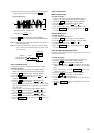
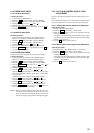
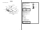
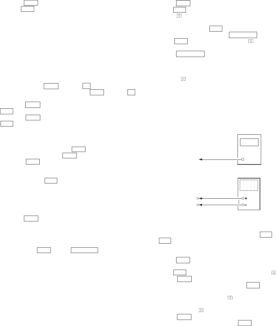
Connection :
Adjusting Procedure :
1. Set the laser power meter on the objective lens of the optical
pick-up. (When it cannot be set properly, press the m button
or M button to move the optical pick-up.)
Connect the digital volt meter to CN105 pin 1 (I+3V) and
CN105 pin 2 (IOP).
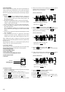
2. Rotate the AMS knob and display “LDPWR ADJUST”.
(Laser power : For adjustment)
3. Press the YES button once and display “LD 0.9 mW $ ”.
4. Rotate the AMS knob so that the reading of the laser power
meter becomes 0.85 to 0.91 mW. Press the YES button after
setting the range knob of the laser power meter, and save the
adjustment results. (“LD SAVE $ ” will be displayed for a
moment.)
5. Then “LD 7.0 mW $ ” will be displayed.
6. Rotate the AMS knob so that the reading of the laser power
meter becomes 6.9 to 7.1 mW, press the YES button and save
it.
Note : Do not perform the emission with 7.0 mW more than 15
seconds continuously.
Laser power
meter
Optical pick-up
objective lens
Digital volt mete
r
BD board
CN105 pin 1 (I+3V)
CN105 pin 2 (IOP)