


19
HCD-XGR6/XGR60
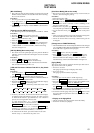
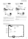
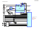
REC Bias Adjustment DECK B
Procedure:
1. Mode: Record
FUNCTION: VIDEO
attenuator
set
MAIN board
MD(VIDEO) IN jack (J701)
L-CH, R-CH
1) 315 Hz
2) 10 kHz
50 mV (– 23.8 dB)
600
Ω
blank tap
e
CS-123
AF OSC
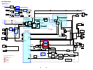
2. Mode: Playback
+
–
set
recorded
portion
MAIN board
CN301 pin
1
(L-CH)
pin
3
(R-CH)
level mete
r
3. Confirm playback the signal recorded in step 1 become speci-
fication values as follows.
If these values are out of specification values, adjust the RV321
(L-CH) and RV322 (R-CH) on the MAIN board to repeat
steps 1and 2.
Adjustment level: The playback output of 10kHz level difference
against 315 Hz reference should ±0.5 dB.
Adjustment Location: MAIN board
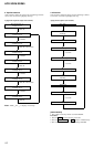
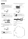
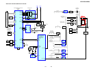
REC Level Adjustment DECK B
Procedure:
1. Mode: Record
FUNCTION: VIDEO
set
MAIN board
MD (VIDEO) IN jack (J701)
L-CH, R-CH
315 Hz, 50 mV (– 23.8 dB)
blank tape
CS-123
600
Ω
attenuator
AF OSC
2. Mode: Playback
+
–
set
recorded
portion
MAIN board
CN301 pin
1
(L-CH)
pin
3
(R-CH)
level meter
3. Confirm playback the signal recorded in step 1 become speci-
fication values as follows.
If these values are out of specification values, adjust the RV351
(L-CH) and RV301 (R-CH) on the MAIN board to repeat steps
1 and 2.
Specification values:
CN301 playback level: 47.2 to 53.0 mV (– 24.3 to – 23.3 dB)
Adjustment Location: MAIN board
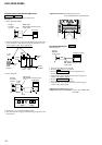
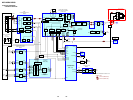
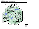
– MAIN BOARD (Component Side) –
1
18
1
15
CN431
CN371
1
3
IN
OUT
MD (VIDEO)
CN301
IC301
IC501
RV321
REC BIAS
L-CH
RV351
REC LEVEL
L-CH
RV301
REC LEVEL
R-CH
RV391
TAPE SPEED
(NORMAL)
RV392
TAPE SPEED
(HIGH)
RV322
REC BIAS
R-CH