


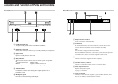
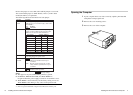
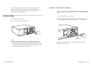
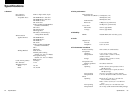
5V+5%
GND
PARITY
R GND L
0
1
2
ID SELECT
PREVENT/ALLOW
TEST MODE
INTERFACE CONNECTOR
AUDIO OUT
F.GND
DC INPUT
12V+10%
-
-
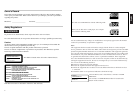
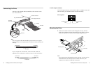
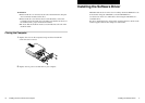
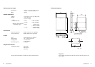
Mounting Screws
Audio Cable
Flat Cable
Connecting the Drive
Attach one end of the flat cable (SCSI cable) to the connector on the
rear of the CDR drive.
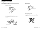
Note
The red edge of the flat cable should be positioned next to the power
supply connector. It is important that this cable be connected firmly and
correctly.
If your computer has a Sound Card, connect the audio cable (not
supplied) to the AUDIO OUT connector at the rear of the CD-R drive.
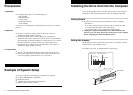
12 Installing the Drive Unit into the Computer
Flat Cable
CD-R Drive
Audio Cable
CD-R DriveSound Card
Interface Card
5V+5%
GND
DEVICE TYPE
L GND R
0
1
2
ID SELECT
PREVENT/ALLOW
TEST MODE
INTERFACE CONNECTOR
AUDIO OUT
F.GND
DC INPUT
12V+10%
-
-
DEVICE TYP
L GND R
0
1
2
ID SELECT
PREVENT/A
TEST MODE
AUDIO OUT
F.GND
Interface Connector
Power Supply Connector
Red Edge
Audio
Cable
Audio Out
Connector
Red Wire
Flat Cable
Sony CDU926S Drive Unit
■ Audio output connector
The audio output connector recommended is Molex 5159PBT contacts and
5051-04 housing or 5103 PBT contacts and 5102-04 housing.
Pin assignment
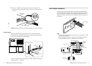
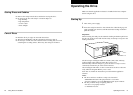
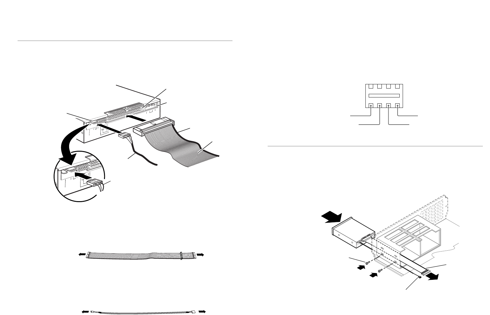
Mounting the Drive
1 Route the flat cable and audio cable through the drive bay from the
front of the computer and insert the CD-R drive into the bay as shown.
Secure the CD-R drive to the frame by using the prepared screws.
Note
If you cannot secure the CD-R drive to the drive bay, you may need to
install slide rails (not included) to the CD-R drive. Refer to your
computer user’s guide for additional information.
Installing the Drive Unit into the Computer 13
Right signal
GND
Left signal
GND