


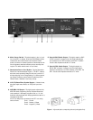

K - Main Power Switch - This switch must be in the “on” posi-
tion for the SFT-1 to operate. When the POWER button (J) has
rendered the unit’s control functions off, this switch allows
power to continue to circulate to sections of the transport so the
unit will operate at maximum efficiency with no warm-up time
required. This switch should remain on at all times.
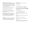
L - Detachable Power Cord Socket - Plug the Detachable
Power Cord into this socket (see Figure 1). The SFT-1 is factory
set for the correct operating voltage for the area in which it is
sold (see shipping box for voltage setting). If a different operat-
ing voltage is required, please contact an authorized Sonic
Frontiers dealer, distributor or the factory directly.
M -
H-P/ST (Glass Fibre) Optical Output - If chosen for use,
this digital output must connect to an ST-Optical input on the
D A C .
N
- AES/EBU XLR Output - This digital output conforms to the
AES/EBU (Audio Engineering Society/European Broadcast
Union) standard. If this output is chosen for use, a 110 ohm
balanced cable terminated with XLR plugs should be used for a
connection to the DAC.
NOTE: The XLR jack pin connectors for the SFT-1 are config-
ured as follows: Pin #1 : Ground
Pin #2 : Positive (+) Phase
Pin #3 : Negative (–) Phase
O -
Coaxial BNC Cable Output - This digital output is a BNC
S/PDIF connector. If chosen for use, this digital output should
be connected to an S/PDIF connector on the DAC. The BNC -
Coaxial cable impedance should be 75 ohms.
P - Coaxial RCA Cable Output - This digital output is an
RCA S/PDIF connector. If chosen for use, this digital output
should be connected to an S/PDIF connector on the DAC. The
RCA - Coaxial cable impedance should be 75 ohms.
Figure 1 - Align socket pins to corresponding holes and push together firmly.
K L M N O P