


6
SONANCE MERLOT
®
M
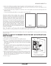
4. Position the included cutout template where the speaker is to be located and pencil an outline on the wall.
• If you are unsure about obstructions, drill a small hole in the center of the outline and insert a coat hanger wire into
the hole to feel-around for possible obstructions.
5. Cut the mounting hole using a keyhole or drywall saw, and run the speaker wires from the mounting hole to the
amplifier location.
• Consult local building codes before running speaker wires through walls.
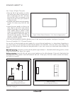
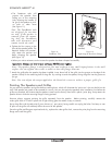
Before Installation: IR Plug
All Sonance Merlot M-series speakers have a plug for
installing an IR receiver into the speaker’s front baffle (see
Figure 8
). In systems where the electronics are placed in an
inconvenient location this allows remote controls to be
aimed at the front of the room instead of at the electronics.
The IR plug is in the form of a bolt and retaining nut. To
remove the plug, unscrew the nut (located behind the baffle,
see
Figure 9
) and remove the bolt. The hole is designed to
receive a Sonance OptiLinQ
®
SMR1 or SMR1P Surface-
Mount IR receiver. Insert the IR receiver through the front of
the speaker baffle and use the nut included with the receiver
to secure it to the baffle.
Note: The speaker’s grille may reduce the effectiveness of the IR receiver. If this occurs, slightly
enlarge the holes in the grille that are directly in front of the IR receiver.
Installation
Sonance Merlot M speakers feature exclusive FastMount
®
tabs and an integral RotoLock
®
mounting system for quick mounting
directly into walls.
CCAAUUTTIIOONN::
TTHHEE
EEDDGGEESS
OOFF
TTHHEE
FFAASSTTMMOOUUNNTT
TTAABBSS
AARREE
VVEERRYY
SSHHAARRPP..
UUSSEE
CCAAUUTTIIOONN
WWHHEENN
HHAANN-
DDLLIINNGG
TTHHEE
SSPPEEAAKKEERR..
1. Remove the paint plug from the speaker.
2. Run speaker wire from each speaker to the amplifier location.
3. Strip ¼” – ½” of insulation from each speaker lead. Twist the strands or tin
the exposed wire with solder to ensure that there are no stray strands. (Stray
strands that touch each other can cause a short-circuit that can damage
your amplifier.)
4. The speaker’s connector posts are spring-loaded. Push the top of each
connector post down to open the connector and insert the exposed wires
into the holes in the posts.
• The speaker’s positive post is labeled with a red dot; the negative post is
labeled with a black dot. Double-check that you connected amplifier “+”
to speaker “+” and amplifier “–” to speaker “–”.
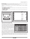
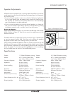
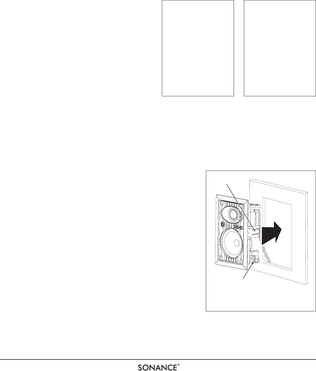
5. Make sure all the RotoLock clamps are in the full clockwise position so that
they are tucked within the mounting hole’s border. Insert the speaker into
the hole in the wall (
Figure 10
). The RotoLock system can accommodate a
maximum wall material thickness of 1¼”.
continued on page 7
Figure 8:
IR Plug
Figure 9:
IR Plug Retaining Nut
RotoLock
®
Clamp
(retracted)
FastMount
®
Tab
Figure 10: Inserting the Speaker
Into the Mounting Hole