


4
SONANCE MERLOT
®
M
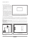
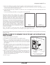
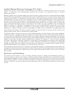
RReeaarr wwaallll mmoouunnttiinngg::
Locate the surround channel speakers on the rear wall, 6 – 10 feet apart, at least 5 feet from the
floor. Center the speakers on the listening location. Use
Figure 5
(below) as a guide.
Note: If the listening position is less than 2 feet in front of the rear wall we do not recommend
mounting the surround speakers in the rear wall. Use ceiling mounting or side-wall mounting
instead.
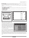
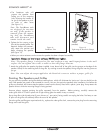
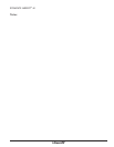
Surround Speakers (7.1-Channel System)
•• LLeefftt && RRiigghhtt SSuurrrroouunndd SSppeeaakkeerrss::
Place the left and right surround speakers directly to the sides of the listening
position, at least 5 feet from the floor.
•• SSuurrrroouunndd BBaacckk SSppeeaakkeerrss::
Place the surround back speakers in the rear wall, between 3 feet and 6 feet apart and at
least 5 feet from the floor.
Use
Figure 6
as a guide.
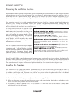
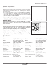
Selecting the Proper Speaker Wire
For the best sound we recommend that you use premium
Sonance MediaLinQ
®
speaker cable, which also complies
with UL fire rating codes. You may also experiment with
audiophile brands of speaker cable and interconnects, but
be sure to check local codes governing wire that may be
installed within walls or ceilings. Different brands of wire
can have different sonic characteristics, and some may be
more compatible with the sonic “signature” of your
various audio system components.
For the best sound you should never use thin-gauge speaker
wire – it will constrict the sound and diminish bass
response. Extra resistance in the speaker wire can make a
speaker sound less dynamic and reduce definition of the
bass frequencies. In extreme cases, it can even attenuate
high frequencies. Also, amplifier power is wasted in thin
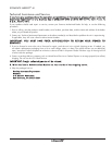
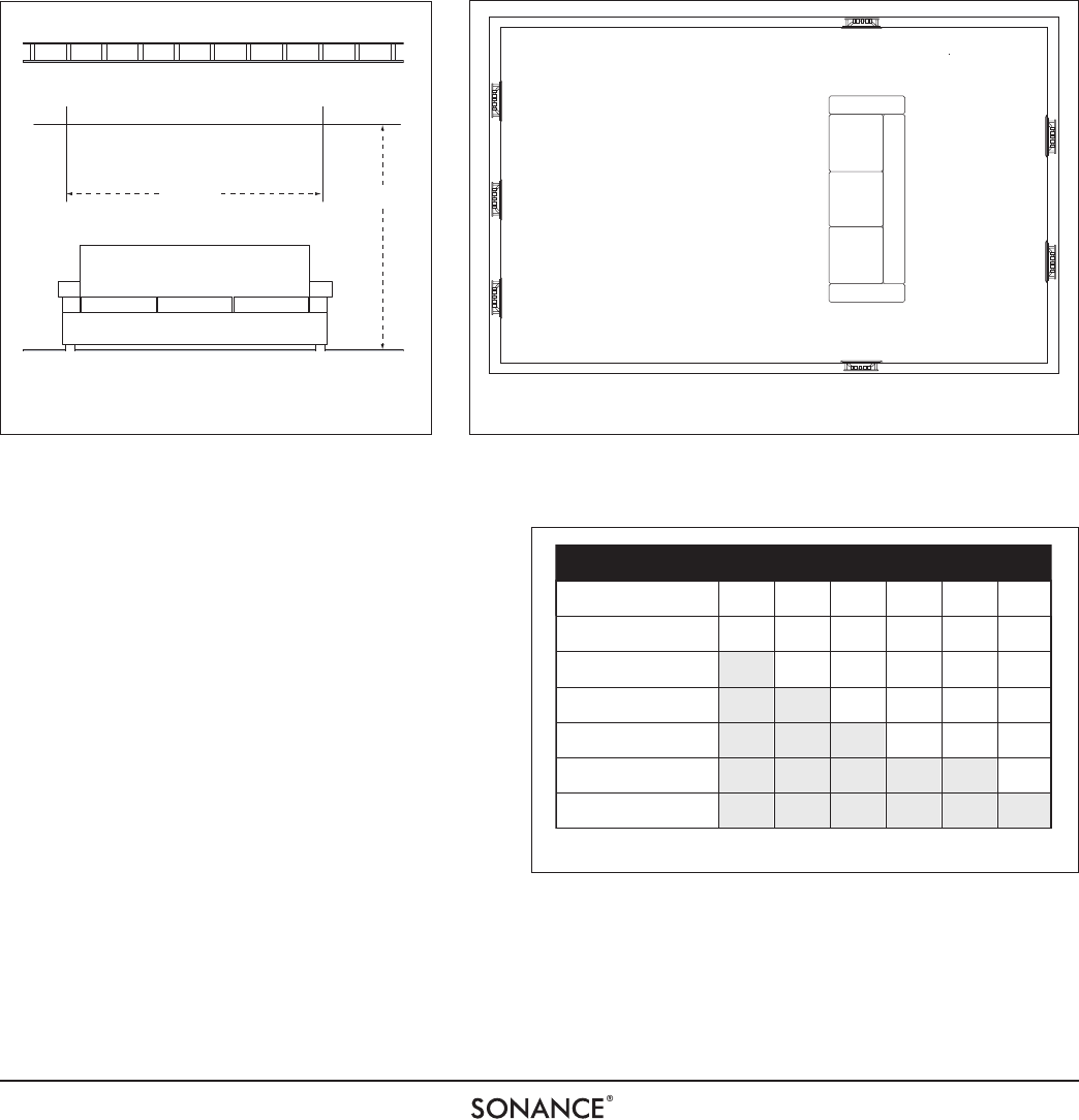
wire with extra resistance, reducing your system’s maximum output level. To prevent degrading sound quality, the total wire
resistance should be less than 10% of the speaker’s impedance. This means that for an 8-ohm speaker, the total resistance
of the wire should be less than 0.8 ohms. Refer to the chart in
Figure 7
when selecting the proper wire gauge for your
system.
Figure 5: Rear Wall Surround Speaker Placement
Right Surround
Left Surround
Left
Front
Right
Front
Center
Left
Back
Surround
Right
Back
Surround
Figure 6: Speaker Placement in a 7.1-Channel System
W
IRE
R
ESISTANCE
IN
O
HMS
VS
. L
ENGTH
OF
C
ABLE
R
UN
Distance in Feet 50' 100' 150' 200' 250' 300'
1.04
.65
.41
.26
.16
.10
18 gauge
16 gauge
14 gauge
12 gauge
10 gauge
20 gauge
2.07
1.30
.82
.52
.32
.20
3.11
1.96
1.22
.77
.49
.31
4.14
2.61
1.63
1.03
.65
.41
5.18
3.26
2.04
1.29
.81
.51
6.22
3.91
2.45
1.55
.97
.61
Figure 7: Speaker Wire Resistance Table