


4
SONANCE CINEMA
®
SELECT
SELECTING THE PROPER SPEAKER WIRE
For the best sound we recommend that you use premium Sonance MediaLinQ
®
speaker cable, which also complies with UL fire rating codes. You may also
experiment with audiophile brands of speaker cable and interconnects, but be sure
to check local codes governing wire that may be installed within walls or ceilings.
Different brands of wire can have different sonic characteristics, and some may be
more compatible with the sonic “signature” of your various audio system
components.
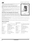
For the best sound you should never use thin-gauge speaker wire – it will constrict
the sound and diminish bass response. Extra resistance in the speaker wire can make
a speaker sound less dynamic and reduce definition of the bass frequencies. In
extreme cases, it can even attenuate high frequencies. Also, amplifier power is
wasted in thin wire with extra resistance, reducing your system’s maximum output
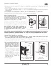
level. To prevent degrading sound quality, the total wire resistance should be less
than 10% of the speaker’s impedance. This means that for an 8-ohm speaker, the
total resistance of the wire should be less than 0.8 ohms. Refer to
Figure 6
when
selecting the proper wire gauge for your system.
PREPARING THE INSTALLATION LOCATION
Building a Backbox into the Wall Stud Bay
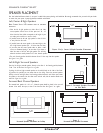
Sonance Cinema Select speakers are designed to provide exceptional performance in a wide variety of enclosure volumes. You can get the very best
performance from your speakers by partitioning a section of the stud bay to form a sealed backbox with a specific internal volume. Building such an enclo-
sure will create a dramatic improvement in your speakers’ bass performance and power handling.
Ideal back box volume requirement for Cinema Select LCR and SUR speakers is 1.5 ft
3
.
Optional Speaker Enclosures
For installations where it isn’t possible to partition the stud bay into a back box, installing optional SymphonyT Acoustic Enclosures (part #91687) will
noticeably improve your speakers’ bass performance and power handling and will significantly reduce sound transmission into adjacent rooms and spaces.
These enclosures are made from ½”-thick MDF and are designed to be installed in new construction only.
To reduce sound transmission into adjacent rooms in installations where it isn’t possible to install a SymphonyT Acoustic Enclosure (such as when you’re
retrofitting the speakers into an existing wall), you can fit the speakers with optional SymphonyT Retrofit Enclosures (part #92342). This enclosure will
noticeably reduce sound “spillover” from the rears of the speakers into adjacent rooms and spaces.
Insulating the Wall Cavity
You can also reduce sound transmission to adjacent rooms and improve speaker performance by inserting a sheet of unfaced fiberglass insulation over the back
of the speaker. To reduce mechanical noise produced by unsupported drywall, install fiberglass insulation in the stud bays adjacent to the speaker location.
Sonafill
®
Sonafill (part #91698) is a retrofittable acoustical treatment system consisting of two pillows and four tiles that virtually eliminates noises produced by resonat-
ing drywall. The tiles have pressure-sensitive adhesive and are installed on the back of the drywall on either side of the speaker between the wall studs; the
pillows are then stuffed in place behind the tiles. The system dramatically improves midbass sound quality and reduces sound transmission into adjacent rooms.
INSTALLING THE SPEAKERS
Before Installation: New Construction
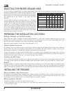
For installations in new construction, Sonance recommends using a SymphonyT FlexBracket (part #92336) to reserve a location for Cinema Select speakers.
The FlexBracket has perforated wings that can be positioned at anywhere around the bracket, and is nailed or screwed to the studs. This serves as a guide
for the drywaller so that the speaker hole will be in the desired location once the drywall is installed.
Before Installation: Retrofit
1. Determine the location for the speaker (see
Speaker Placement
on page 3).
2. Perform an obstruction survey to be certain that there are no studs, conduit, pipes, heating ducts, pocket doors or air returns in the wall cavity that
will interfere with the speaker.
Wire resistance in Ohms vs. length of cable run
Distance in Feet 50' 100' 150' 200' 250' 300'
1.04
.65
.41
.26
.16
.10
18 gauge
16 gauge
14 gauge
12 gauge
10 gauge
20 gauge
2.07
1.30
.82
.52
.32
.20
3.11
1.96
1.22
.77
.49
.31
4.14
2.61
1.63
1.03
.65
.41
5.18
3.26
2.04
1.29
.81
.51
6.22
3.91
2.45
1.55
.97
.61
Figure 6: Speaker Wire Resistance Table