


2
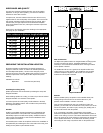
WIRE GAUGE AND QUALITY
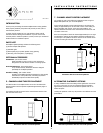
PREPARING THE INSTALLATION LOCATION
Sonafill
Insulating the ceiling cavity
Retrofit
The total wire resistance should be less than 10% of the speaker
impedance. If using an 8 ohm speaker, your total wire resistance
should be no more than 0.8 ohms.
In simple terms, the extra resistance from the wire will have a very
negative affect on the sound quality of the speaker. The sound can be
less dynamic, definition of bass frequencies can be reduced, and in
extreme cases, the high frequencies can be attenuated. Amplifier
power is also wasted in the wire, reducing the maximum output level
of the system.
Please refer to the following chart when deciding on the appropriate
wire gauge for your installation.
Wire resistance in Ohms vs. length of cable run
Distance in Feet
50' 100' 150' 200' 250' 300'
.86
.65
.43
.27
.17
.11
18 gauge
16 gauge
14 gauge
12 gauge
10 gauge
20 gauge
1.73
1.30
.85
.54
.34
.22
2.59
1.94
1.28
.81
.51
.33
3.45
2.59
1.71
1.08
.68
.44
4.32
3.24
2.14
1.35
.85
.56
5.18
3.89
2.56
1.62
1.02
.67
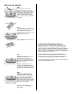
Speaker performance can be enhanced by insulating the cavity with
fiberglass insulation.
When installing speakers in a ceiling, it is best to lay a sheet of unfaced
fiberglass insulation over the back of the speaker.
To further improve the sound quality, install insulation in the bays
adjacent to the speaker location. This will reduce noise produced by
the unsupported drywall.
Sonafill is a retrofitable acoustical treatment for loudspeakers that
virtually eliminates the noise produced by resonating drywall and
dramatically improves mid-bass sound quality. Sonafill also reduces
room-to-room noise especially in multi-channel installations where
many speakers are installed.
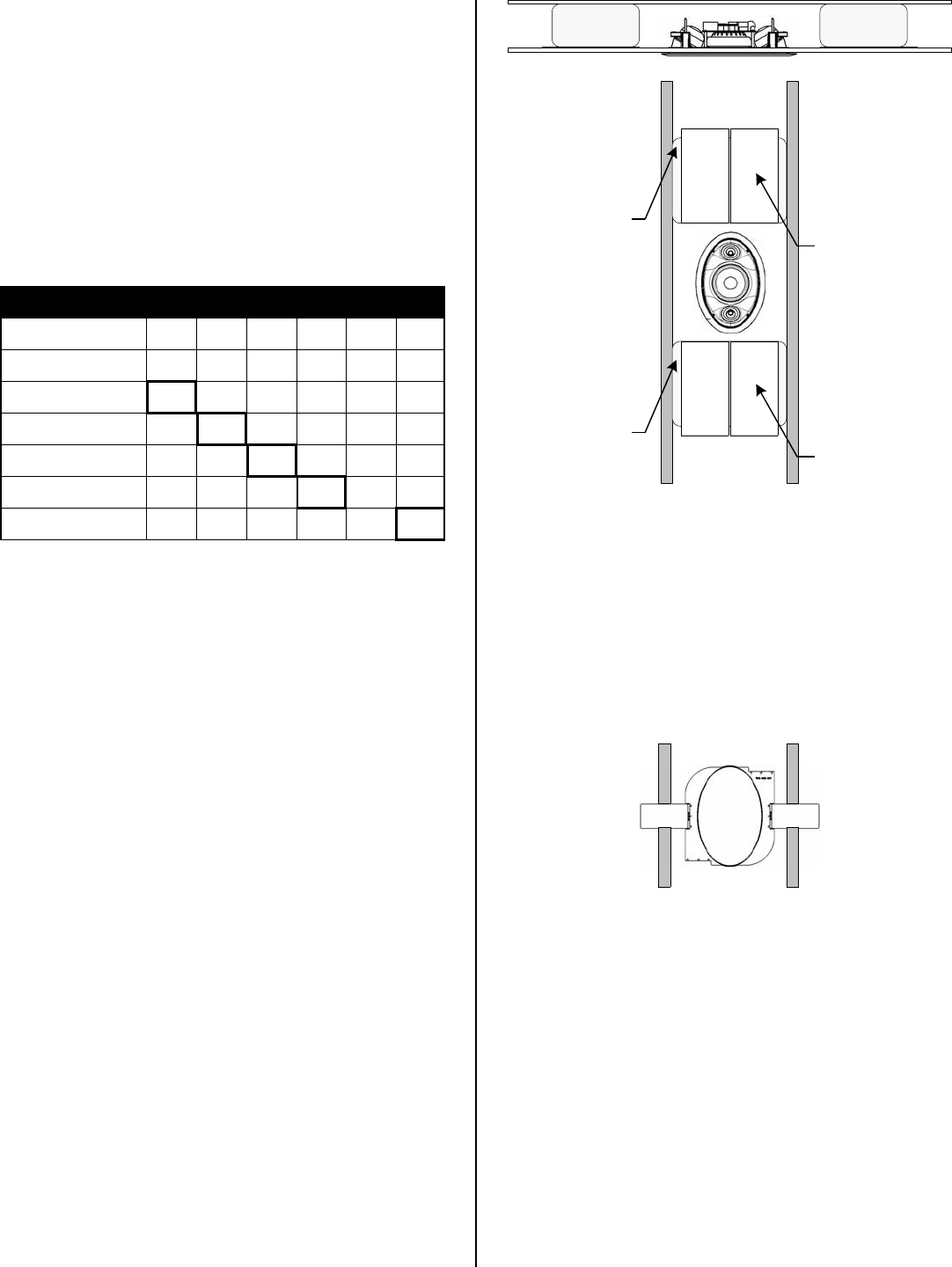
The Sonafill system consists of two pillows and four tiles. Installation is
accomplished by first adhering the tiles to the inside of the cavity, then
stuffing the two pillows in place behind the tiles.
The Sonafill System
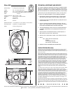
All Sonance speakers are designed to be relatively insensitive to
changes in enclosure volume. To achieve the ultimate performance
from the Ellipse SUR speaker, a section of the ceiling bay can be
sectioned off to form a back box. Building this enclosure will create a
dramatic improvement in the quality of bass response and power
handling.
Ideal Back box volume:
Ellipse SUR 1.00 cubic feet (28.3 liters)
New Construction
Acoustic Pillow
Acoustic Pillow
Damping Tiles
Damping Tiles
Ellipse FlexBracket
The Ellipse LCR speaker features an integral FlexBar mounting system
for quick mounting into ceilings. The Ellipse FlexBracket is only
necessary in new construction installations when reserving a location
for the speaker is desired.
The FlexBracket will serve as a guide for the drywall installer when
cutting holes for in-ceiling speakers. The FlexBracket can be nailed,
screwed or stapled to the joists so that the hole is in the desired
location once the drywall is installed.
With the FlexBar system, the speaker can be installed directly into
existing ceilings. Once the hole is cut and the cable is run, the
speakers can be installed in a matter of seconds.
Once you have determined the area you would like to locate your
speakers, you will need to do an obstruction survey. Before you cut the
hole for the speaker, be certain no joist, conduit, pipe, heating duct or
air return will interfere with the speaker.
A cut out template is provided in the packaging of the speaker.
Position the template where the speaker is to be located and pencil an
outline on the ceiling. If you are unsure about obstructions drill a small
hole in the center of the circle and insert a coat hanger into the hole to
feel for possible obstructions. If no obstructions are found, proceed
with cutting the hole using a drywall saw and run the speaker wires.
®
TM