


20
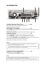
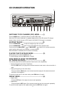
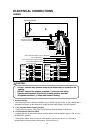
ELECTRICAL CONNECTIONS
WIRING
CAUTION
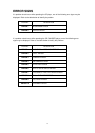
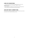
1. Antenna Socket
• Insert the plug from the antenna installed in your vehicle into this socket. (If your vehicle has a
dual antenna system, a dual antenna to single antenna cable adaptor may be required.)
2. + 12V Constant Power Supply (Yellow)
• Connect this wire to the +12V power terminal which receives power continuously.
3. +12V Accessory/Switched (Red)
• Connect this wire to the terminal which receives power while the ignition switch is ON or in the
ACCESSORY position.
• If the ignition switch does not have on ACC position, connect this wire to a +12V power
terminal which receives power continuously. (Same as item 2.)
Antenna Socket
CONNECTOR SOCKET
CD CHANGER
+12V Constant Power Supply (Yellow)
Power Antenna/Amplifier Turn On (Blue/Red)
2-SPEAKER SYSTEM
AND SIRIUS RECEIVER
+12V Accessory/Switched (Red)
Speaker
Front Right
Rear Right
Speaker
Front Left
Speaker
Rear Left
Speaker
REAR LINE OUT CABLE
I.R REMOTE SENSOR SOCKET
(BLACK)
4-SPEAKER SYSTEM
(WHITE/BLACK)
- -
(VIOLET/BLACK)
(GRAY/BLACK)
(VIOLET)
+ +
+
-
+
-
(GRAY)
+
-
(WHITE)
+
-
Speaker
Speaker
Rear Right
Front Left
Speaker
Front Right
Ground Wire (Black)
(GREEN/BLACK)
-
+
-
(GREEN)
+
Rear Left
Speaker
(WHITE/BLACK)
- -
(VIOLET/BLACK)
(VIOLET)
+ +
(WHITE)
(GRAY/BLACK)
(GRAY)
+
+
- -
+
-
+
-
(GREEN/BLACK)
(GREEN)
- -
+ +
Lch White
Rch Red
(Brown)
(Gray)
(Gray)
(Brown)
FRONT LINE OUT CABLE
(BLACK)
Rch Red
Lch White
Rch Red
Lch White
AUN IN CABLE
(BLACK)
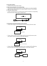
•
DO NOT connect any speaker wires to the m
etal body or chassis of the
vehicle.
• DO NOT connect the speaker common (–) wires to each other.
• Connect each speaker wire directly to each speaker terminal.
• All speaker common (–) wires must remain floating.