MOON P 5.3 Stereo Preamplifier
Rear Panel Connections
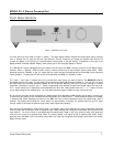
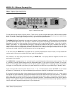
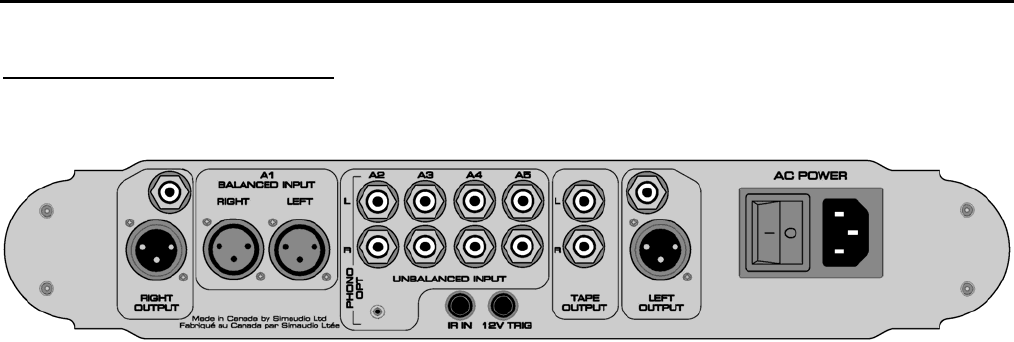
Figure 3: MOON P5.3 Rear panel
The rear panel will look similar to Figure 3 (above). There are four (4) pairs of single-ended inputs on RCA connectors labeled
A2, A3, A4 and A5. The left channel inputs are located on top and the corresponding right channel inputs are located directly
below. To the left of these single-ended inputs is one (1) pair of balanced inputs labeled A1.
The MOON P5.3 Stereo Preamplifier has three pairs of outputs; One single-ended pair of RCA connectors and one balanced
pair, each labeled ‘Right Output” and “Left Output”’, located on either side of the previously aforementioned inputs; They are
designated for output to a power amplifier with either balanced XLR or single-ended RCA inputs. A third pair of outputs,
labeled “Tape Output” on single-ended RCA connectors, located directly besides the A5 input is intended as an input to a
recording device such as a cassette tape deck or CD-Recordable Player. Keep in mind that the output level on the ‘Tape
Output’ is fixed and cannot be adjusted by the P5.3’s volume control. All RCA input and output connectors on the rear panel
have been color coded: ‘white’ for the left channel and ‘red’ for the right channel.
In the event that your MOON P5.3 is equipped with the previously described phono section module, the input labelled A2
must be used to connect your turntable interconnect leads to this preamplifier.
Don’t hesitate to use high quality interconnects with your MOON P5.3. Poor quality cables can degrade the overall sonic
performance of your system.
Your MOON P5.3 is equipped with a 1/8” mini-jack input for use with aftermarket infrared remote control receivers. The “IR
in” connector is centrally located directly below the single-ended inputs. To the right of this jack is another 1/8” mini-jack
which is a 12 Volt trigger output intended for use with a power amplifier equipped with a 12 Volt trigger input. The purpose of
this trigger is to remotely power up and down your power amplifier at the same time as your P5.3 using its “Standby” switch.
Finally on the right side is the main power switch (“0”=off, “1”=on), the IEC receptacle, labeled “AC POWER” for the included
AC power cord. Alternatively, you may use a dedicated high-performance AC power cord designed for power amplifiers.
All rear panel connectors have been chosen because they provide the best possible connections for your unit. A poor contact
will degrade the signal substantially, and plugs and sockets should all look clean and free of dirt and corrosion. The easiest
way to clean them is to remove the cables from their sockets and push them back in again. This procedure requires that your
Stereo Preamplifier and the rest of your components be completely turned off. Not heeding this warning may result in serious
damage to your equipment. Special contact cleaning fluids and enhancers should not be used, as they deposit a difficult to
remove residue which degrades the performance of your components.
____________________________________________________________________________________
Rear Panel Connections 11


