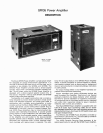
SR105
Power Amplifier
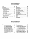
TABLE OF CONTENTS
Section Page
...............................
SPECIFICATIONS ii
DESCRIPTION
..................................
1
OPERATING INSTRUCTIONS
........................
Functional Identification 3
..................
General Operating Instructions
3
........................
Mounting and Ventilation 4
Thermal Overload
.............................
4
...........................
Power Requirements 4
...................
Functional Circuit Description 4
Input Connections
.............................
4
............................
Output Connections 6
Amplifier-to-Speaker Impedance Matching
.........
8
Output Voltage Meter
...........................
9
..........................
Basic Operating Hints 10
SPECIAL OPERATING INSTRUCTIONS
Adding
SRlO5A Amplifiers in a
...................
70-Volt System (Cascaded) 10
..........................
Bridging Connections 11
Adding Headphone Jack to Speaker Connections
...
11
SERVICE INSTRUCTIONS
..............................
Amplifier Service 12
Section Page
............................
Replacement Parts 12
.............................
Fuse Replacement 12
..........................
Bottom Plate Removal 12
................................
Cover Removal 12
............................
Lamp Replacement 12
...................
Dc Output Balance Adjustment 12
Output Voltage Meter Calibration
.................
12
...................
Printed Circuit Board Removal 13
Small Signal and Predriver Transistors
............
14
.............................
Driver Transistors 14
.............................
Output Transistors 15
Diodes
.......................................
15
..........................
Diode Bridge Rectifier 15
Checking Transistors and Diodes
.................
15
SR105B Amplifier Conversion for 70-Volt Output
....
15
Service lllustrations
............................
17
Guarantee
....................................
17
Shipping Instructions
...........................
17
....................................
PARTS LIST 19
CONDENSED OPERATING INSTRUCTIONS
.........
27
ARCHITECTS' AND
ENGINEERS' SPECIFICATIONS
...............
27
SR105
Power Amplifier
LlST OF ILLUSTRATIONS
Figure Page
...........
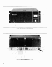
1 SR105 Power Amplifier Front Panel 2
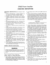
2 SR105 Power Amplifier Rear Panel
...........
2
3
SR105 Power Amplifier Dimensional
.........................
Outline Drawing 4
4
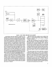
SR105 Power Amplifier Block Diagram
........
5
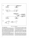
5 Input Connections
.........................
6
6
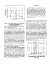
Output Power vs
.
Load lmpedance from
2 Ohms to 32 Ohms
......................
7
7
70-Volt Output Power vs
.
Direct Output Load
Impedance from
4
Ohms to 100 Ohms
.......
7
8
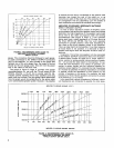
Recommended Wire Gauge vs
.
Amplifier-to-
Speaker Distance: Direct Output
...........
8
9
Recommended Wire Gauge vs
.
Amplifier-to-
Speaker Distance: 70-Volt Output
(SR105A Only)
..........................
8
Figure Page
10 70-Volt System Attenuator
...................
11
11
Bridged Amplifier Connections
...............
11
12 Headphone Jack for Speaker Connections
.....
11
13
SR105 Power Amplifier Top View, Cover
Removed
(SR105A Model Shown)
..........
13
14
SR105 Power Amplifier Bottom View.
Cover Removed
(SR105A Model Shown)
.....
14
15
70-Volt Conversion: Added Circuitry
..........
16
.....
16 70-Volt Conversion: Transformer Mounting 17
...........
17 70-Volt Conversion: Internal Wiring 18
....
18 Main Circuit Board Parts Location Diagram 22
....
19 Filter Circuit Board Parts Location Diagram 22
.....................
20 Transistor Lead Codes 23
.......
21 SR105 Power Amplifier Circuit Diagram 25


