


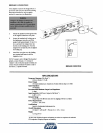

BRIDGED
CONNECTION
If
the amplifier is used in the Bridged MtKie, to
prevent the risk of electric shock the following
instructions describe the only acceptable
method of connection (see illustration).
Voltages in the Bridged Connection ate
hazardous to
life.
Make
all
amplifier-to-
speaker connections with
AC
power discon-
nected. Refer
senicing to qualitied senice
~ewnnel.
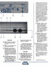
1.
Thread the speaker lead through the hole
in the supplied connector cover plate.
2.
Loosen the insulated red locking cap on
the binding post, strip the end of the
speaker lead (approximately 19
mm [3/4
in.]
),
and
insert
the stripped wire into
the hole in the
bindmg post. Twist the
stripped wire around the post and tighten
the locking cap.
Attach the cover plate over the binding
post terminal and fasten it
with
the
supplied screws.
NOTE:
To ensure correct Bridged Mode speaker
polarity, connect the plus
(+)
terminal of
Channel 1 only to the plus speaker terminal and
connect the plus terminal of Channel 2 only to
the minus
(
-
)
speaker terminal.
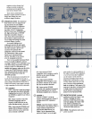
CONNECTION
DETAIL
BRIDGED
CONNECTION
SPECIFICATIONS
Frequency Response
(Flat Mode
'
)
20 Hz to 20 kHz
+
0.5 dB
Power Output
100 watts
minimum
per channel into
8
ohms
with
less than 0.1
%
THD
Input Impedance
100 kilohms
Recommended
Minimum
Output
Load
Impedance
4 ohms
Input Sensitivity
(Full
Power Output in Flat Mode')
0 dBV (1.0 V)
Dynamic Range
Greater
than
100
dB
from
noise level to clipping (300
Hz
to 20 kHz)
Power Requirements
120 Vac
f
lo%, 60 Hz
CeMcations
Listed by Underwriters Laboratories Inc.
Overall Dimensions
102mmHx429mmWx356mmD(4x 16%~ 14in.)
Weight
12.3 kg (27 lb)
'In other modes Frequency Response
and
Sensitivity are tailored to complement the
individual
HTS
Loudspeakers' Frequency Response
and
Sensitivity