


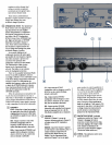
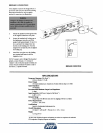


INDICATORS
@
POPER;
Red light in the pushbutton
Power switch illuminates to indicate
power is on.
@
SIGNAL:
Green light illuminates when a
signal is present in the channel.
@
OVERLOAD:
Red light illuminates to
indicate limiting when the Protection
Defeat switch
is
out,
or to indicate clip-
ping when the Protection Defeat switch
is pushed
in.
In normal
use
with HTS5O
SURROUND LEFT SURROUND RIGHT,
SUBWOOFER OR BRIDGED.)
If
speaker locations are reassigned,
remove the tabs by carefully prying one
comer out of the slot with a pointed
instrument. The tab
can
then
be
removed
with the
hgertips. Take care not to
scratch or damage the amplifier front
hish when removing the indicator tab.
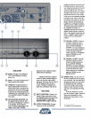
BACK
PANEL
lo;dspeakers, the overload light
will
turn
on occasionally for high-level dialogue or
music
peaks.
binding posts that
will
accept any of the
following methods
of
connection: bare
wire wrapped around the post, bare wire
inserted through the hole in the post,
spade lug around the post, pin connector
through the hole in the post, or banana
plug inserted in the jack These output
connectors will accommodate most
high-
performance audio cables. (Gold ,080-
inch diameter pins soldered to the loud-
speaker cables and inserted under the
binding post hex caps [fastened finger-
tight] are the most reliable connection.)
To maintain proper speaker polarity in
the completed HTS system, it is
extremely
important that each plus
(+)
amplifier output ted is connected
only to a plus speaker
ted, and each
minus
(-)
amplifier output terminal is
connected only to a minus speaker
terminal.
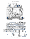
@
INPUT
CONNECTOss:
Chml
1
and
Channel
2
input connectors are heavy-
duty gold-plated phono (RCA
type)
jacks.
@
~IWOR
TM
0
SLOB:
snap
the supplied Indicator Tabs into these
slots when the loudspeaker
is
connected
to the amplifier. The tabs show the
speaker location
correspondmg to each
@
CHANNEL
1
OUTPUT:
Both plus
and minus terminals are used in
normal two-channel operation to
drive an
HTSSOCF, HTSSOLRS,
HTSSOSW or any other loudspeaker.
Only the plus terminal of Channel
1
is used as the plus or high side
output connection to a loudspeaker
when the
HTSSOSPA is in the
BRIDGED MODE
'
.
Use
only-&el
1
input
when
BRIDGED
MODE
output
is selected.
@
OUTPUT CONNECTORS
All
output
connectors are five-way gold-plated
@
CIIANNEL
2
OUTPUT:
Both
plus
and minus terminals are used in
channel (LEFT,
RIGHT,
CENTER,
:swum=
-
-
-
-
-
-----
-----
-
---
-----
tllr-
-
normal two-channel operation to
drive an
HTSSOCF, HTSSOLRS,
HTS5OSW or any other loudspeaker.
Only the plus terminal of Channel 2
is used as the minus or low side
output connection to a loudspeaker
when the
HTSSOSPA is in the
BRIDGED MODE
'
.
@
EXTERNAL
FUSE:
The lOA, 250
V
Slo-
Blo fuse accessible from the rear panel is
user replaceable.
If
the fuse should blow,
disconnect the power cord, and remove
the fuseholder and fuse by pressing
inward and rotating counterclockwise.
Replace the
fuse
only with one of the
same
type,
same amperage and voltage
rating.
If
the fuse should blow a second
time, do not replace it
again.
Contact the
Shure Service Department or other
qualified service
personnel to correct
the problem.
'See
Bridged
Connection
instructions.