


3
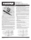
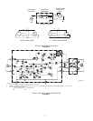
Dimensions
See Figure 5
(13/16
in.)
20 mm
(5-7/16 in.)
138 mm
1
1.9 mm
(15/32 in.)
31.8 mm
(1-1/4 IN.)
98 MICROPHONE
ILP–1 PREAMPLIFIER (SM98A)
WM98: 1.12 m (3 ft 8 in.)
SM98A: 4.6 m (15 ft)
OVERALL DIMENSIONS
FIGURE 5
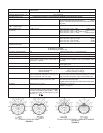
TA3F
TA4F
(WA330)
WM98 ST
ANDARD TEST CIRCUIT
FIGURE 6
1
2
4
3
5V
20 K
V out
1.0
µF
100 K
+
–
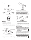
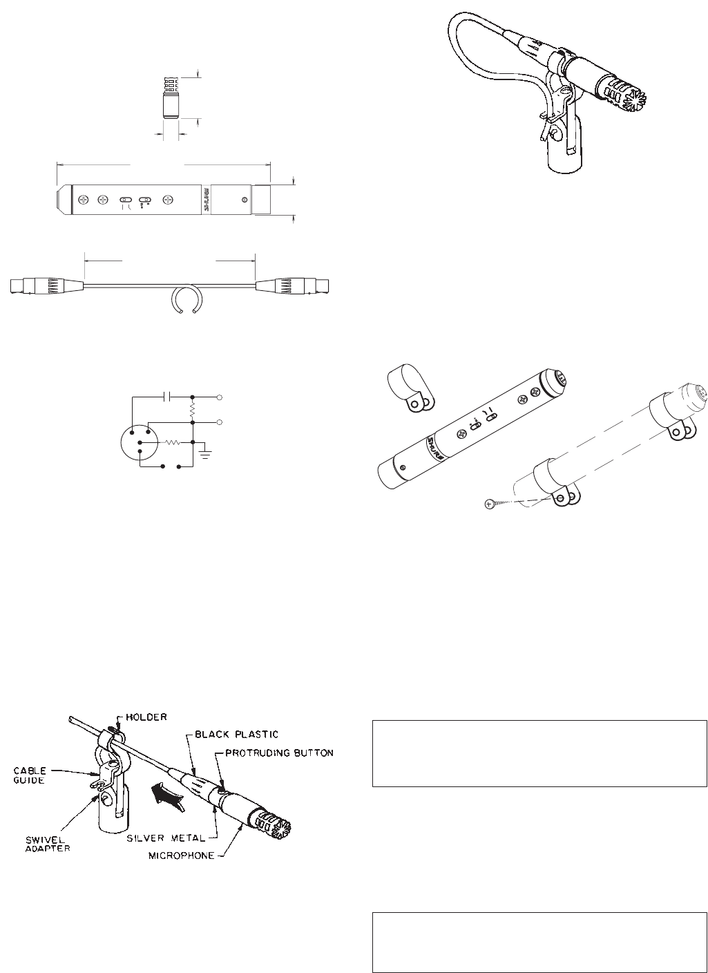
INSTALLATION
To
mount the 98 in the supplied swivel adapter:
1.
Mount the adapter on a microphone stand.
2.
Attach the microphone to the connector
.
3. Slip
the cable through the slot in the adapter
. Slide the connec
-
tor
back through the hole until the protruding black cable lock
button
is in the open slot and the
back of the microphone itself
stops
flush with the front of the holder
. Only the silver metal seg
-
ment
of the connector is held by the holder (see Figure 7).
SWIVEL ADAPTER MOUNTING
FIGURE 7
4. Slide
the cable through the slot in the cable guide and make a
large
loop (see Figure 8). Then route the cable away from the
stand to prevent transmission of noise and vibration through
the
cable.
CABLE RETAINED IN GUIDE
FIGURE 8
5. T
ilt the adapter to aim the microphone as desired.
6. To
remove the microphone without disturbing the swivel adapt
-
er
and cable, reach into the open slot of the adapter and press
the
cable-lock button while disengaging the microphone.
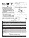
PREAMPLIFIER PERMANENT MOUNTING (SM98A)
The
supplied mounting clamps are intended to hold the pre
-
amplifier in place in permanent installations (see Figure 9). Use
either
one or two clamps depending on location and application.
MOUNTING
CLAMPS – SM98A PREAMPLIFIER
FIGURE 9
PREAMPLIFIER SWITCHES
The
preamplifier case contains two miniature recessed slide
switches.
In the Lo Cut position, the Flat/Lo Cut switch
provides
a
12 dB rollof
f below 80 Hz (see Figure 1). The ef
fects of the 0/+10
dB
Gain switch are described in the
Preamplifier Output Clipping
Level
specifications.
INSTALLING THE A98SPM
The A98SPM Supercardioid Polar Modifier is supplied with
the
SM98A and is an optional accessory for the
WM98. T
o mount
the
microphone in
an A98SPM Polar Modifier
, proceed as follows.
IMPORTANT
The white internal element of the A98SPM is es-
sential to maintaining the supercardioid polar pat-
tern.
Do
not
remove it!
1. Unscrew
the rear support from the front support by turning the
rear
support counterclockwise (from bottom). See Figure 10.
2. Insert
the microphone (cable
not
connected) into the rear sup
-
port
with its connector end contacting the support.
3. Attach
the front and rear supports together by turning the
rear
support
clockwise (from bottom). T
ighten
suf
ficiently to prevent
rattling.
CAUTION
Do
not overtighten. Damage to the internal element
may
result.