


MANIPULATION
FUNCTION
DISPLAY
(RX)
37EM 203, Publ. 10/94 engl
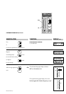
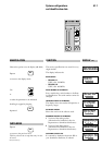
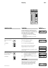
LED indicators 4.2.1
REMOTE
+ 20
dB
+ 20 dBu
+ 12 V
- 12 V
+ 5 V
DC - A
DC - B
OL - A
OL- B
POWER
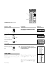
LED DISPLAY
The three upper LEDs light up if the in-built
power supply unit operates perfectly
+ 12 V supply voltage = 12 V
- 12 V supply voltage = -12 V
+ 5 V supply voltage = 5 V
If one LED switches off, please replace the
complete power module and return it for fault
finding.
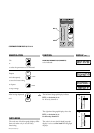
'The other four LEDs serve to monitor the
antenna boosters connected (e.g. AB 1036 TV):
DC-A The switch on input module A is set to ON. The
antenna booster is powered by the EM 1046
system
DC-B The switch on input module B is set to ON. The
antenna booster is powered by the EM 1046
system
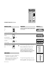
OL-A (Overload) The current across antenna socket A
exceeds 150 mA! Short circuit! Check your
antenna booster.
OL-B (Overload) The current across antenna socket B
exceeds 150 mA! Short circuit! Check your
antenna booster.