


EM 3031/EM 3032
RF Wireless Systems | 3000 Series Receivers
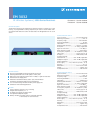
EM 3031 and EM 3032
With the EM 3031 single receiver and EM 3032 twin receiver, Sennheiser offers
two 19” high-quality RF receivers which have excellent operational reliability
and are extremely user-friendly. Combined with a suitable hand-held or bodypack
transmitter, they form a studio-quality radio link. Both receivers use true diversity
technology to reduce drop outs to an absolute minimum and ensure interference-
free operation.
Due to the wide switching bandwidth of the EM 3031 and EM 3032 receivers (24 MHz
for the UHF variant, 7 MHz for VHF) and due to their up to 32 receiving frequencies
you can easily switch to unused frequencies in case of interference on a selected
channel. The EM 3031 and EM 3032 receivers have been designed for demanding
show and broadcasting applications and are ideally suited for large multi-channel
systems.
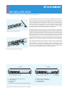
With the GA 3030 AM antenna mount, the antenna sockets can be relocated at the
receiver front, for example if the rear of the rack is closed. If you need to choose
an antenna position away from the receivers, Sennheiser offers the A 12 AD UHF
active directional antenna or the A 1031-U passive omni-directional antenna for the
UHF range and the A 2 P passive omni-directional antenna for the VHF range. The
EM 3031 and 3032 receivers output the audio signal via an XLR-3 socket at the
rear. The level control serves to adjust the AF signal level and adapt it to the sub-
sequent mixing console or amplifier.
The receiver display indicates the chosen receiving frequency or, optionally,
the channel number which it has been assigned. You can also read off the field
strength of the incoming RF signal in µV and the deviation of the audio signal (i.e.
the modulation level of the RF signal) in %. Both RF and AF display have a peak
warning in case the signal strength becomes excessively high. Short peak periods
are not critical. If, however, the audio signal is overmodulated very often and for
quite some time, the sensitivity of the transmitter must be reduced. The AF display
is additionally provided with a “peak-hold” function, i.e. peak values are displayed
for some time so that it becomes easier to detect them.
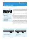
Operating controls of the EM 3031 and EM 3032 – front panel
1 3
8 9 104 5 6 7
2
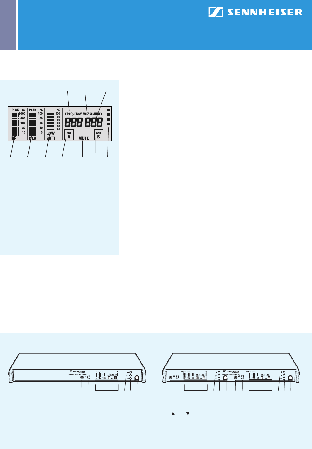
1 “FREQUENCY MHz” display
2 “CHANNEL” display
3 Alphanumeric main display
4 10-step level display for incoming RF signal,
with peak warning
5 10-step level display for incoming AF signal,
with peak warning
6 6-step display for transmitter battery status,
with “Low Batt” warning
7 Diversity antenna A active
8 Squelch active (MUTE)
9 Diversity antenna B active
10 Frequency groups display
Reading off the LC display
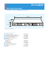
EM 3031 EM 3032
1 1/4” headphone output jack socket
2 Volume control for headphone output
3 Multi-function LC display
4 and buttons for selecting the receiving
frequency/channel number
5 SET button for menu selection and storage
6 On/off switch
1 2 3 4 5 6 1 2 3 4 5 6 1 2 3 4 5 6