


The EM 3031 and EM 3032 receivers are fitted with an adjustable RF squelch, which
mutes the audio output when the antenna voltage drops below the chosen thresh-
old. The squelch can be adjusted between 0 and approx. 100 µV. When the squelch
has been triggered, the “MUTE” warning will light up on the receiver display. The
receivers are additionally equipped with an AMF advanced muting function.
This muting function is triggered when the RF signal suddenly drops by approx.
50 dB. The receiver will then be muted for about 3 seconds to avoid the annoying
crackling noise which is caused when a transmitter is switched off.
The EM 3031 and EM 3032 receivers have a headphone output for monitoring the
incoming audio signal; the monitoring signal is mono. Sennheiser’s closed HD 25
headphones are an ideal choice for monitoring purposes. In order to enable monitor -
ing even in unfavourable conditions (e.g. low AF signal level from the transmitter)
and with high ambient noise (on the stage, for example), the signal from the
headphone output is up to 30 dB louder than the LINE output signal. However, this
may lead to distortion if the level of the incoming signal is quite high and if the
volume control is turned up. In this case, turn back the volume until the distortion
disappears. If the sound remains distorted, the transmitter itself is overmodulated.
The Sennheiser transmitter range includes many models which transmit battery
status information. The EM 3031 and EM 3032 receivers are able to receive this
status information. They display the remaining battery or accupack capacity of the
transmitter in %. When the battery is going flat and the remaining capacity lasts for
only 20 to 30 minutes of operation, the “LOW BATT” warning on the display starts
flashing. You should immediately replace the transmitter battery.
EM 3031/EM 3032
RF Wireless Systems | 3000 Series Receivers
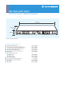
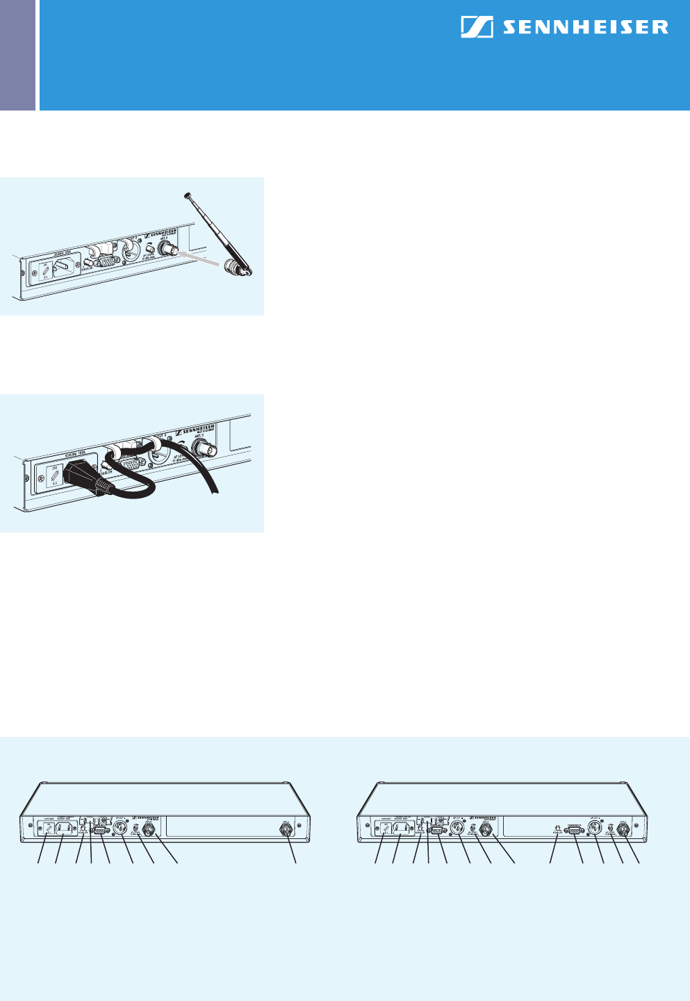
Operating controls of the EM 3031 and EM 3032 – back panel
EM 3031 EM 3032
7 Fuse holder and mains voltage selector
8 Mains connector
9 Squelch control
10 Cable grip
11 Service interface (not used during normal operation)
12 Balanced XLR-3 audio output
13 AF level control for audio output
14 Antenna socket B
15 Antenna socket A
7 8 9 1110 12 13 14 15 7 8 9 1110 12 13 14 159 11 12 13
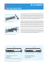
Mounting the telescopic antennas
Using the cable grip for the mains cable