


6
Guided Tour - UM1
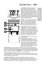
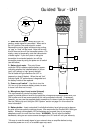
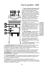
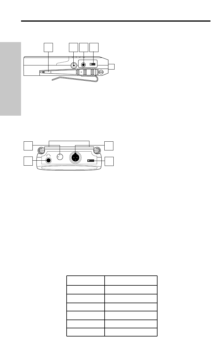
9: DC input - This jack will accept a DC
input voltage of 6 - 13 volts (inner connection
[tip] positive, outer connection [sleeve]
ground) from your video camera, if available.
Connect the optional Samson AC300R
adapter here to charge a rechargeable 9-volt
Ni-Cad battery.
10: Unbalanced output* - Use this unbalanced (1K Ohm max.) 1/8" (3.5 mm) mini-phone
jack when connecting the UM1 to consumer (-10) audio equipment. Wiring is as follows:
tip hot, sleeve ground. If your video camera has stereo audio inputs, you’ll need to use a
Y-adapter that has a 1/8" (3.5 mm) mini-phone plug at one end and dual male RCA-type
plugs at the other end.
11: Audio Output Level switch - Sets the audio output level of both the balanced and
unbalanced outputs (see #10 above and #14 below) to -30 dBm (mic level), -20 dBm, or
-10 dBm (line level). See the “Setting Up and Using the UM1 System” section on page 8 in
this manual for more information.
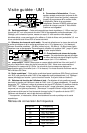
12: Level control - This knob sets the level
of the audio signal being sent to the
headphones output (see #13 below).
13: Headphones output - Connect a
stereo headphone to this standard 1/8" (3.5
mm) mini-phone jack in order to monitor the
signal being output by the UM1. We recommend the use of 30 ohm headphones.
The level of the headphone signal can be set by adjusting the Level control (see #12
above). Maximum output is 240 mW @ 30 ohms).
14: Balanced output* - Use this electronically balanced low impedance (600 Ohm)
mini-XLR jack when connecting the UM1 to professional (+4) audio equipment. Pin wiring
is as follows: Pin 1 ground, Pin 2 high (hot), and Pin 3 low (cold).
15: Meter switch - This three-position switch determines the function of the front-panel
UM1 meter (see page #2 on previous page). In the left “RF” position, the meter indicates
the strength of the incoming RF signal. In the center “BATTERY” position, the meter
indicates relative battery power, showing whether the installed battery is at low (red), mid
(yellow) or high (green) strength. (Note: When the red “low” indicator lights, performance is
degraded and the battery needs to be replaced). In the right “OFF” position, the meter is
disabled altogether, thus conserving battery power.
* If required, both the unbalanced and balanced outputs can be used simultaneously.
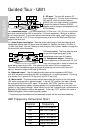
UM1 Frequency Conversion Chart
Channel Frequency
U1 801.375 MHz
U2 801.875 MHz
U3 803.125 MHz
U4 803.750 MHz
U5 804.500 MHz
U6 804.750 MHz
ENGLISH
30 20 10
LEVELOUT UNBAL
DC INPUT
109 118
PHONES
LEVEL
O
U
T
P
U
T
B
A
L
A
N
C
E
D
METER
RF OFF
12
13
14
15
BATT.