


Guided Tour - UR-5/UR-5D
Front Panel
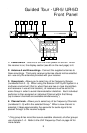
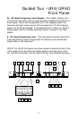
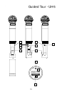
5: Display section - Shows you information about the current status of
your receiver.
5a: “A”/“B” LEDs - When signal is being received, one of these LEDs
(which shows you whether the “A” or “B” channel is currently being
used) will be lit. A computer chip inside the receiver constantly scans
the two and automatically selects whichever is receiving the strongest,
clearest signal. This “true diversity” switching is completely inaudible,
but it effectively increases overall range while virtually eliminating
potential interference and phase cancellation problems.
5b: “Available” LED - When lit, the selected Group and Channel (as
determined by the Group and Channel knobs) is available for use.
When off, the selected Group and Channel is unavailable and cannot be
used. See the reference chart on page 24 for more information.
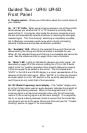
5c: “Mute” LED - Lights to indicate the absence of carrier signal. As
described on page 20 of this manual, setting the UT-5 or UH-5 Audio
switch to the “on” position operates a tone squelch feature by causing
a 38.4 kHz signal to be added to the carrier. The illuminated word
“MUTE” in the UR-5 and UR-5D display is a visual representation of the
absence of this 38.4 kHz signal. When “MUTE” is lit, either the transmit-
ter Audio switch is in the “off” position or the currently selected Group
and Channel do not match that of the transmitter.
5d: RF (Radio Frequency) Level display - This “ladder” display (simi-
lar to the VU bar meter used on audio devices) indicates the strength of
the UHF signal being received. When all five segments are lit, the
incoming signal is at maximum strength; when only the left-most seg-
ment is lit, the incoming signal is at minimum strength. If no segments
are lit, no signal is being received; check to ensure that the transmitter
and receiver are set to the same Group and Channel (see the “Trouble-
shooting” section on page 21 for more details).
6