


4
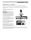
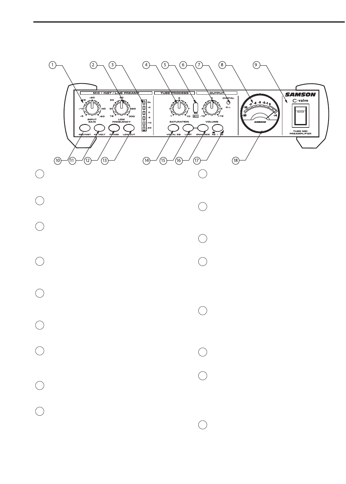
C valve Layout
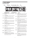
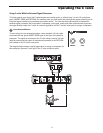
1 INPUT GAIN – Rotary control used to adjust the
input level.
2 LOW FREQUENCY – This rotary control is used to
set the EQ cut off point for the Low Cut filter.
3 INPUT METER – Six segment LED VU meter dis-
plays the input level after being affected by the
Gain control.
4 SATURATION – Rotary control used to adjust the
total amount of harmonic overtones generated
by the tube circuit.
5 PILOT LIGHT - Illuminated indicator that rises in
intensity, and when fully lit, signifies the tube cir-
cuit is ready for operation.
6 VOLUME – Rotary knob used to control the over-
all Output level.
7 Digital Overload - LED indicator, which when
illuminated, displays the digital clipping point of
the Analog to Digital converter.
8 VU METER – Classic round analog VU meter dis-
plays the amount of output level.
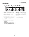
9 POWER SWITCH – Heavy-duty rocker switch
which, when pressed to the “on” position, lights
the internal green LED, indicating the unit is pow-
ered up and ready for operation.
10 MIC/INST switch – This switch is used to select
the proper input operating level for either a
microphone or a line/instrument signal source.
11 48 VOLT – When pressed in, the switch will illu-
minate red indicating the 48-volt phantom
power is on.
12 PHASE – LED backlit switch which will invert the
phase of the mic or instrument input.
13 LOW CUT SWITCH – Used to engage the vari-
able low-cut filter, which attenuates or rolls-off
the low frequency at a rate of 12 dB per octave
starting at the point set by the Low Frequency
control knob.
14 VOCAL EQ - When pressed in, the push switch
activates the Vocal EQ circuit providing a pre-set
equalization curve for “sweetening” the signal
with a subtle, but useful, airy high-end lift .
15 LIMIT SWITCH – When engaged, the LED lights
indicating the Limiter circuit is activated.
16 ENHANCE - When pressed in, the switch acti-
vates the Enhance circuit which helps restore
the high frequencies that can be lost when the
signal is being protected by the on-board LIM-
ITER.
17 48/96 SWITCH - LED backlit switch which is
used to select the sampling frequency of the
internal A-to-D converter for either 48 or 96
kiloHertz operation.
Front Panel Layout