


5
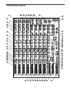
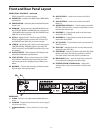
Front Panel Controls
FRONT PANEL
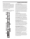
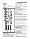
1 MIC IN
– Input connector for Low-Noise Microphone
pre-amp.
2 LINE IN–Input connector for Line level inputs.
3 INSERT – 1/4-inch TRS (TIP/RING/SLEEVE) connector
providing send and receive channel patch point for
outboard effects.
4 GAIN
– Used to set the input level of the mic pre and
line input.
5 LOW CUT – Bass roll off switch at 75Hz used to elimi-
nate unwanted low end rumble and hum.
6 HIGH FREQUENCY
– Controls the high band of the
Channel Equalizer, +/- 15 dB at 12KHz.
7 MID CUT/BOOST – This control knob provides +/- 15
dB of boost or cut at the frequency set on the MID
SWEEP control on the mono input channels.
8 MID SWEEP – Control knob used to set the center
frequency of the mid band of the Channel Equalizer.
9 LOW FREQUENCY – Controls the low band of the
Channel Equalizer, +/- 15 dB at 80Hz.
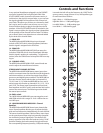
10 AUX 1 – Auxiliary send that can be used with an
external effects processor, or to create a cue or moni-
tor mix.
11 PRE / POST switch
– Used to configure Aux 1 signal
routing from a Pre fader to a post fader send.
12 AUX 2/DSP – Post-fader auxiliary send that can be
used with an external effects processor, or to create a
cue or monitor mix, or to send a signal to the internal
DSP.
13 PAN – Controls the channel’s position between left
and right in the stereo bus.
14 3/4 MUTE LED
– When illuminated, the display indi-
cates that the input channel is assigned to the ALT3/4
bus and is muted in the Left /Right Main Mix bus.
15 3/4 / MUTE switch
– When engaged, the input chan-
nel is assigned to the ALT3/4 bus and is muted in the
Left / Right MAIN MIX bus.
16 SOLO LED
– When illuminated, the display indicates
that the input channel is assigned to the SOLO bus.
17 SOLO switch – When engaged, the input channel is
assigned to the SOLO bus.
18 PEAK – Red LED will illuminate indicating when the
GAIN has been adjusted too high.
19 LEVEL
– Audio taper fader provides smooth control
of level changes.
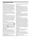
20 +4 / -10 switch – Used to set the line input sensitiv-
ity from –10dB when the switch is pressed in to +4dB
when this switch is out.
21 RIGHT LINE – 1/4-inch phone input connector for the
right line input for the stereo channels.
22 LEFT/MONO LINE - 1/4-inch phone input connec-
tor for the Left Line input for the stereo channels or a
mono input.
23 ALT 3/4 OUTPUTS jacks – Balanced, 1/4-inch phone
connectors carrying the signal from the ALT 3/4 bus.
24 CONTROL ROOM OUTPUT
– Left and Right Control
Room output connectors for connecting a monitor
system.
25 MAIN MIX OUTPUT (1/4-inch) – Left and Right Main
Mix balanced output 1/4-inch TRS connectors.
26 MAIN MIX OUTPUT (XLR)
– Left and Right Main Mix
balanced output XLR connectors.
27 AUX RETURN 1 – Left and right input jacks for con-
necting to the outputs of external line level sources
like those from effects processors.
28 AUX RETURN 2 – Left and right input jacks for con-
necting to the outputs of external line level sources
like those from effects processors.
29 FOOTSWITCH JACK
– 1/4-inch phone jack for con-
necting a standard footswitch used to turn the inter-
nal DSP effects on and off.
30 PHONES JACK
– Connect stereo headphones here.
31 AUX SEND 2 – Line level output from the Auxiliary 2
bus.
32 AUX SEND 1
– Line level output from the Auxiliary 1
bus.
33 2 TRACK OUTPUTS – Connect to the input of a DAT,
Cassette, Mini Disk or Hard Disk Recording system.
34 2 TRACK INPUTS – Connect the output from a DAT,
Cassette, Mini Disk or Hard Disk Recording system.
35 2 TRK LEVEL – Control knob used to set the level of
the source connected to the 2-track input.
36 VARIATIONS – Control knob used to select one of the
sixteen variations for each of the sixteen DSP effect
programs.
37 PROGRAMS – Control knob used to select one of the
sixteen DSP effect programs.
38 DSP PEAK
– LED indicator illuminates when the input
signal to the internal DSP is reaching an overload
level.
39 DSP MUTE switch – Used to turn the internal DSP
effects on and off.
40 ALT 3/4 TO MIX – Routes the ALT 3/4 to the Left /
Right MAIN MIX outputs. Use the ALT3/4 Level (55) to
set the volume.
41 2 TRK TO MIX
- Routes the Left / Right 2 track inputs
to the Left / Right MAIN MIX outputs. Use the 2 TRK