


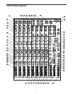

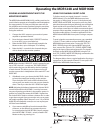
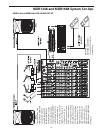

12
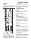
Controls and Functions
DSP with 256 presets. The presets are organized in sixteen
Program banks, each with sixteen variations. The Variation
control knob is used to select one of the sixteen variations
for each of the sixteen DSP effect Programs.
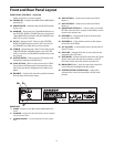
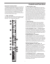
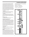
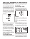
38 - PEAK (DSP INPUT) LED
LED indicator illuminates when the input signal to the
internal DSP is reaching a clipping level.
39 - DSP MUTE switch
This switch is used to turn the internal DSP effects on and
off. When the DSP MUTE switch is pressed in, the internal
DSP effects are turned off and when the switch is pressed
out, the DSP effects are on.
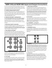
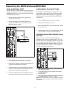
2 TRACK INPUT AND OUTPUT
The MDR1248 and MDR1688’s 2 Track section provides the
connections for playback and recording for an external
device such as a DAT, cassette recorder, CD or Mini Disk.
Main Mix Assign Switches
The next two switch functions are used to select addition-
al sources that can be combined with the Main Left and
Right mix and sent to the main Left and Right Outputs.
40 - ALT 4/3 TO MIX switch
The ALT 3/4 TO MIX switch is used to assign the ALT 3/4
mix bus to the MAIN mix bus. If you push the ALT 3/4 TO
MIX button, all the channels with their ALT 3/4 switch
pressed in will be routed to the left and right MAIN out-
puts and the level will be controlled by the 3/4 LEVEL con-
trol knob and MAIN LEVEL fader.
41 - 2TK TO MIX switch
The 2TR TO MIX switch is used to assign the 2TR input to
the MAIN mix bus. If you push the 2TR TO MIX button, the
signal present at the 2 TRACK IN will be routed to the left
and right MAIN output and the level will be controlled by
the 2TK LEVEL control knob and MAIN LEVEL fader.
Control Room and Headphone Assign Switches
The next three switch functions are used to select addi-
tional sources that can be heard in the headphones and
sent to the Left and Right Control Room Outputs.
42 - MAIN MIX switch
The MAIN MIX switch routes the Left / Right MAIN mix bus
to the CONTROL ROOM / PHONES outputs. Use the Left /
Right MAIN MIX Level faders (48) and PHONES level fader
(49) to set the volume.
43 - ALT 3/4 switch
The ALT 3/4 switch routes the 3/4 mix bus to the CONTROL
ROOM / PHONES outputs. Use the ALT 3/4 LEVEL control
knob (32) and PHONES level fader (49) to set the volume.
44 - 2 TK IN switch
The 2TR IN switch is used to assign the 2TR input to the
Control Room output. If you push down the 2TK IN button,
signal will be routed into the left and right Control Room
MASTER SECTION (continued)
output and will be adjusted by the CR / PHONES control
fader.
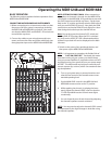
45 - Phantom Power LED
This LED illuminates indicating that the 48 volt phantom
power is applied to the microphone pre-amps enabling
use with condenser microphones. The +48V LED will light
up when the Phantom Power switch (located on the rear
panel) is switched to the ON position.
46 - POWER LED
The Power LED lights up to indicate that the main POWER
switch (located on the rear panel) is on.
47 - Output Level Meters
The OUTPUT LEVEL METERS allows you to monitor the
level of the signal which is being sent to the MAIN MIX
jacks.
48 - MAIN MIX - Fader Control
The master MAIN controls are the overall volume controls
for the left and right mix bus. These line level signals are
output from the MAIN MIX jacks.
49 - PHONES / CR
The PHONES / CR control is used to set the level sent to the
control room outputs, and also to the headphone jack.
NOTE: To avoid distortion, adjust the Main Level control so
that the 0 indicator LED lights occasionally.