


12
Connections
1
3
2
2
3
1
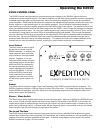
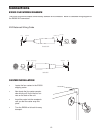
Hot
Cold
Female XLR
Male XLR
Hot (2)
Cold (3)
Common (1)Common
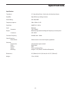
Hot
Cold
Hot (2)
Cold (3)
Common (1) Common
Solder Points End View
End View Solder Points
12
3
21
3
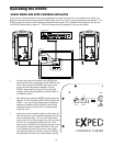
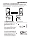
XLR Balanced Wiring Guide
The EX500’s input and outputs utilize industry standard XLR connectors. Below is a detailed wiring diagram for
the EX500 XLR connectors.
EX500 XLR WIRING DIAGRAM
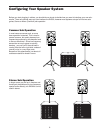
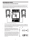
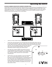
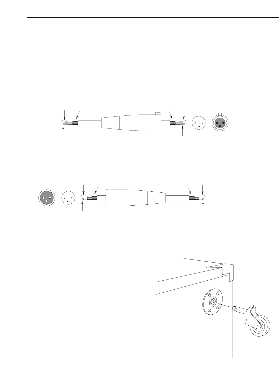
CASTER INSTALLATION
• Locate the four casters in the EX500
shipping carton.
• Now locate the four caster recepta-
cles which you’ll find in the four cor-
ners on the back of the unit.
• Insert the caster into the receptacle
until you feel the caster snap into
place.
• Turn the EX500 on its back for easy
transport.