


8
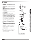
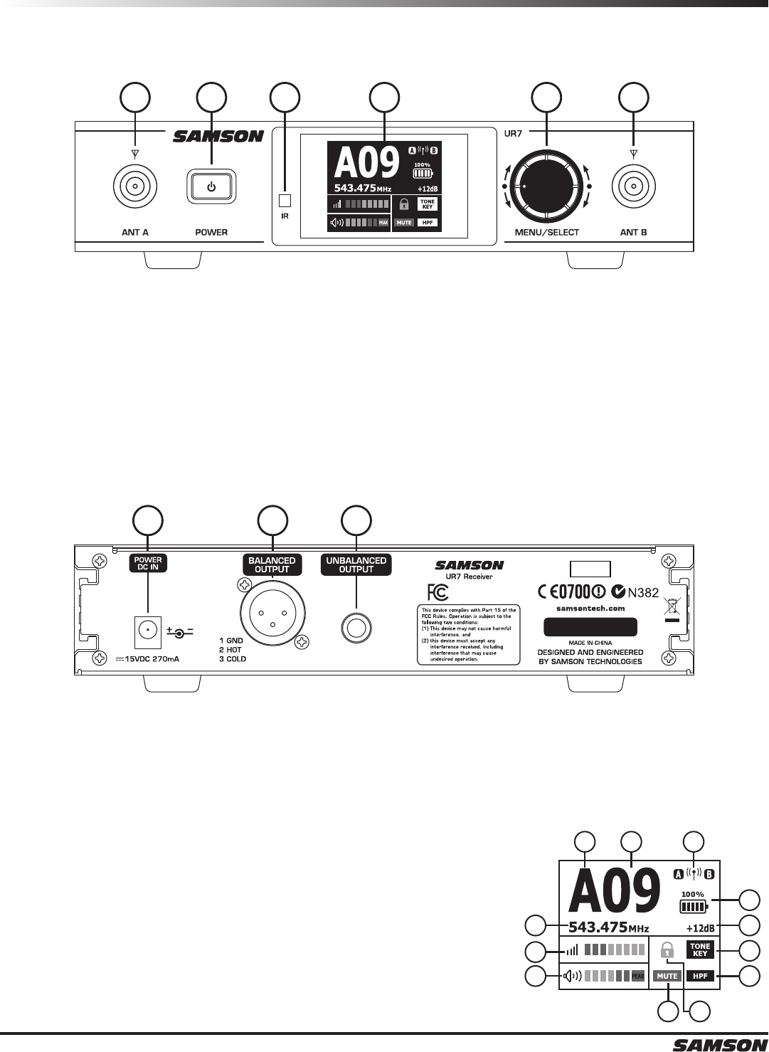
UR7 Receiver Callouts
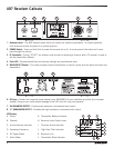
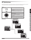
A. Group
B. Channel
C. Active Antenna Indicator
D. Operating Frequency
E. RF Signal Meter
F. Audio Meter
G. Transmitter Battery Indicator
H. Receiver Audio Output Level
I. Tone Key Active Indicator
J. High Pass Filter Indicator
K. Receiver Lock
L. Transmitter Mute Indicator
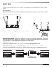
1. Antennas Jacks - The BNC antenna jacks allow full rotation for optimum placement. In normal operation,
both antennas should be placed in a vertical position.
2. POWER Switch - Press and hold this to power the receiver on or off. A quick press of the button will move
back through the menus.
3. IR Transmitter - During “IR SET” an infrared code (similar to selecting a channel with a TV remote) is used to
set the transmitter channel.
4. Color LCD - Displays transmitter and receiver settings and performance data.
5. MENU/SELECT Control - This rotary encoder control knob/button is used to control and set menu functions and
parameters.
1 12 3 4 5
FREQ:
518-546.9MHz
Tested To Comply With
FCC Standards
For Home Or Oce Use
6 7 8
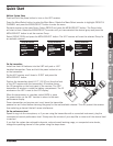
6. DC Input - Connect the supplied power adapter here. WARNING: Do not substitute any other kind of power
adapter. Doing so can cause severe damage to the UR7 and will void your warranty.
7. XLR BALANCED OUTPUT - Electronically balanced, microphone-level output.
8. ¼” UNBALANCED OUTPUT - Unbalanced high impedance instrument-level output.
A B C
G
HD
E
F
I
J
KL
LCD Display