


11
Samson AirLine
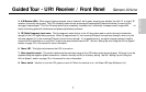
on the following page) to -30 dBm (mic level), -20 dBm, or -10 dBm (line level).
See the “Setting Up and Using the AirLine System” section on page 16 in this
manual for more information.
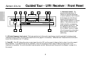
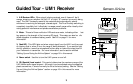
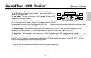
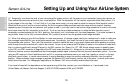
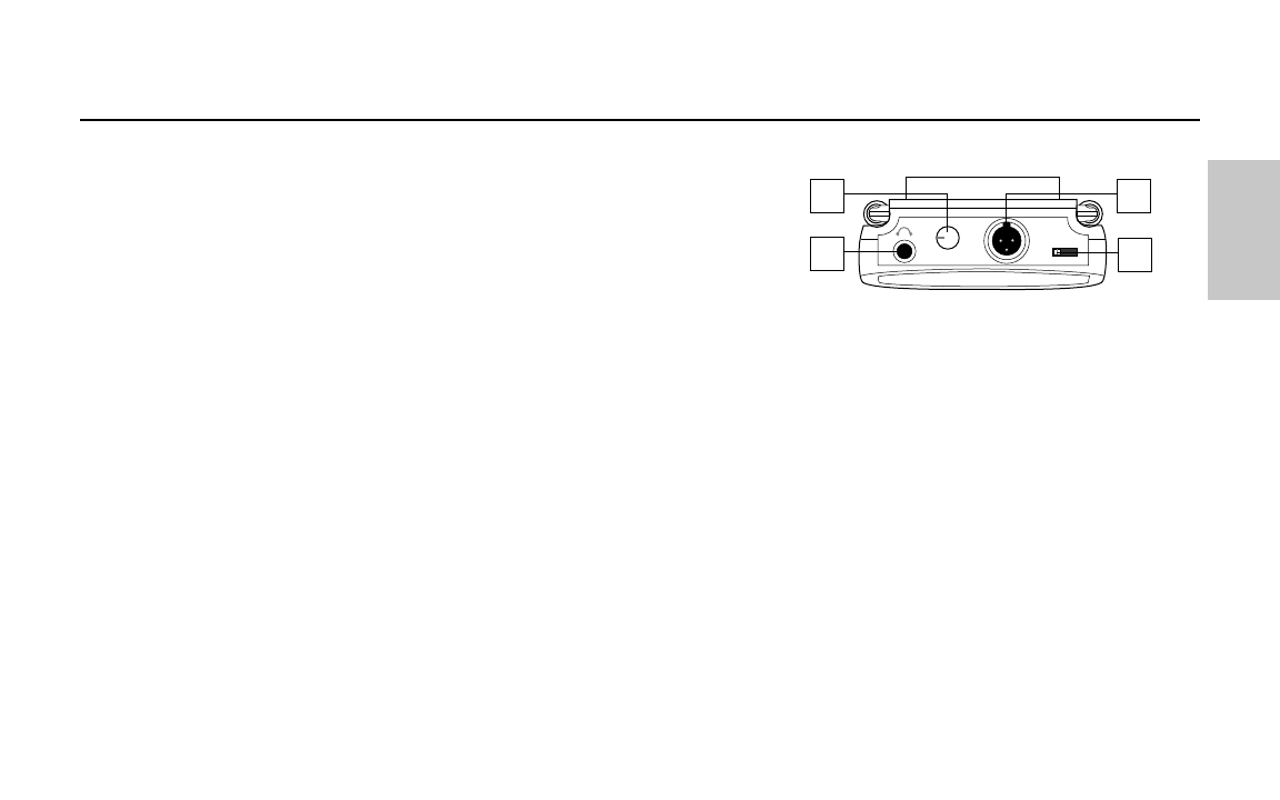
12: Level control - This knob sets the level of the audio signal being sent to the
headphones output (see #13 below).
13: Headphones output - Connect a stereo headphone to this standard 1/8"
(3.5 mm) mini-phone jack in order to monitor the signal being output by the UM1.
We recommend the use of 30 ohm headphones. The level of the headphone signal can be set by adjusting the Level control (see
#12 above). Maximum output is 240 mW @ 30 ohms).
14: Balanced output* - Use this electronically balanced low impedance (600 Ohm) mini-XLR jack when connecting the UM1 to
professional (+4) audio equipment. Pin wiring is as follows: Pin 1 ground, Pin 2 high (hot), and Pin 3 low (cold).
15: Meter switch - This three-position switch determines the function of the front-panel UM1 meter (see page #2 on page 9). In
the left “RF” position, the meter indicates the strength of the incoming RF signal. In the center “BATTERY” position, the meter indi-
cates relative battery power, showing whether the installed battery is at low (red), mid (yellow) or high (green) strength. (Note:
When the red “low” indicator lights, performance is degraded and the battery needs to be replaced). In the right “OFF” position,
the meter is disabled altogether, thus conserving battery power.
* If required, both the unbalanced and balanced outputs can be used simultaneously.
Guided Tour - UM1 Receiver
PHONES
LEVEL
O
U
T
P
U
T
B
A
L
A
N
C
E
D
METER
RF OFF
12
13
14
15
BATT.
ENGLISH