


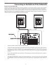

Operating the Resolv A Series
Resolv A Series Control Panel - continued
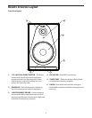
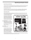
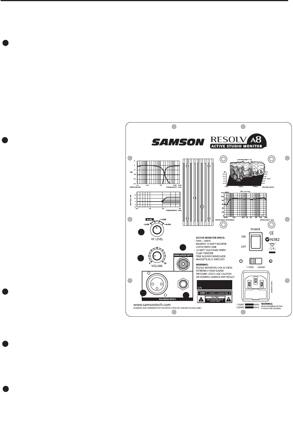
HIGH FREQUENCY LEVEL CONTROL
The four-position High Frequency Level control switch is used to adjust the monitor's high-frequency
response, providing four equalization curves to select from. By using the High Frequency Level con-
trol, the Resolv A Series’ high frequency response is adjusted with the application of a high-end tilt
(equalization circuit) centered at 12kHz, with selectable levels of –3dB, 0dB (flat), + 3dB and +6dB. You’ll
find that the change is very subtle. Many mix engineers prefer the sound of near field monitors with a
little lift in the high frequency response, some like more focus on the midrange, and therefore, desire
a flatter or rolled off high frequency response. The best way to set the controls is what sounds good to
you. Therefore, you should experiment with the various settings to find the combination of the High
Frequency Level and Volume controls you like. To do this, play several CD’s of music that you are familiar
with. Remember, if you think you’re getting lost, the Resolv A Series is flat when the High Frequency Level
control is set to the “0” position.
VOLUME CONTROL
The volume control is used to adjust the
overall output level of the Resolv A Series.
When operating the unit for the first time,
start with the volume control set all the
way off. Slowly raise the Volume control
to reach a comfortable listening level.
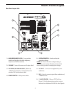
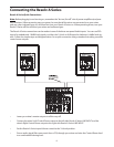
The Ins and The Outs
The Resolv A Series features a full comple-
ment of input connectors providing easy
installation with a variety of audio devices
like recording consoles, hard disk record-
ers, CD players and computer sound
cards, to name a few. The following sec-
tion details the Resolv A Series's input
connectors. In addition, there is a detailed
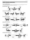
cable-wiring diagram on page 12.
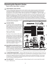
BALANCED XLR AUDIO INPUT (A6 and
A8 only) - The Resolv A Series features a
female XLR connector that will accept bal-
anced or unbalanced +4dBU line level sig-
nal. If you are using a mixer that has bal-
anced outputs on XLR connectors, you can make the connections via standard XLR (microphone) cable.
1/4-INCH PHONE AUDIO INPUT – A balanced TRS (Tip, Ring, Sleeve) 1/4-inch phone plug is used to con-
nect balanced or unbalanced line level signals. The 1/4-inch input is a switching jack, so when a 1/4-inch
connector is inserted into the jack, the RCA and/or XLR inputs are switched off and the 1/4-inch input
is switched on. This provides a convenient patch-point for quick insertion of a secondary input signal
source for testing or expanded operation.
RCA AUDIO INPUT – The RCA input accepts unbalanced signals used to connect signals from unbal-
anced –10dBV devices.
3
4
5
6
7
1
2
3
4
5
6
7
1
2
3
4
5
6
7
1
2
3
4
5
6
7
1
2
3
4
5
6
7
1
2
3
4
5
6
7
10