


4
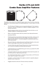
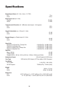
Guided Tour - Front Panel
-12
-9
-6
-3
0
+3
+6
+9
+12
-15 +15
100Hz 10K
160 31580
160 31580
+12
-12
0
+12
-12
0
630 1.25k
1.25k
2.5k
2.5k630
6.3k
6.3k
PASSIVEACTIVE
BASSVOLUME TREBLE
INPUT
CD
POWER
GRAPHIC EQUALIZER LIMITER PHONES
0
1
2
3
4
5
6
7
8
9
10
-12
-9
-6
-3
0
+3
+6
+9
+12
-15 +15
0
1
2
3
4
5
6
7
8
9
10
A100
1
2
3
4
5
6
78
9
11
10
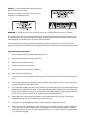
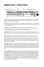
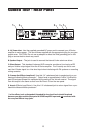
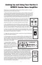
1. Active - Connect your bass guitar to this standard 1/4" unbalanced jack. This A Series
Input was designed to handle the signals from hotter bass pickups if your bass has active
electronics (that is, if it has a battery).
2. Passive - Connect your bass guitar to this standard 1/4" unbalanced jack. The A Series
Input was designed to handle low-level signals if your bass has passive electronics (that is,
if it has no battery)
3. CD Input - Your A Series amplifier features a CD input which you can use with a
portable CD player, cassette, mini disk or MP3 player. You can use the CD input to jam
with pre-recorded tracks or to learn a riff from a favorite recording.
4. Volume control - This is the overall volume control. For best signal-to-noise ratio, keep
the output of your bass at or near maximum and adjust the A Series Volume to the desired
level.
5. Bass EQ control - This control provides approximately 15 db of cut or boost at 100 Hz,
with a peak (bell) curve. When the knob is at the 12 o’clock (“0”) position, there is no
boost or attenuation (that is, flat response). As it is turned clockwise from the “0” position,
the frequency area is boosted; as it is turned counterclockwise from the “0” position, the
frequency area is attenuated. For more information, see the “Using Equalization” section
on page10 in this manual.
6. Treble EQ control - This peaking control provides approximately 15 db of cut or boost at
5 kHz. When the knob is at the 12 o’clock (“0”) position, there is no boost or attenuation
(that is, flat response). As it is turned clockwise from the “0” position, the frequency area is
boosted; as it is turned counterclockwise from the “0” position, the frequency area is atten-
uated. For more information, see the “Using Equalization” section on page 10 in this man-
ual.
7. Graphic Equalizer - These sliders allow you to “draw” the tonal response of the system
by adding 15 dB of boost or attenuation to ten different narrow-band frequency areas (30
Hz, 80 Hz, 160 Hz, 315 Hz, 630 Hz, 1.25 kHz, 2.5 kHz, and 6.3 kHz), affecting the main
output signal of the A70 and A100. When a slider is at its center detented (“0”) position,
the selected frequency area is unaffected (it is said to be flat). When a slider is moved up
(above the “0” position, towards the “+12” position), the selected frequency area is boost-
ed, and when it is moved down (below the “0” position, towards the “-12” position), the
selected frequency area is attenuated. For more information, see the “Using Equalization”
section on page 11 in this manual.