


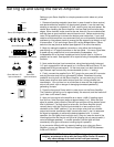
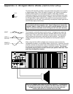
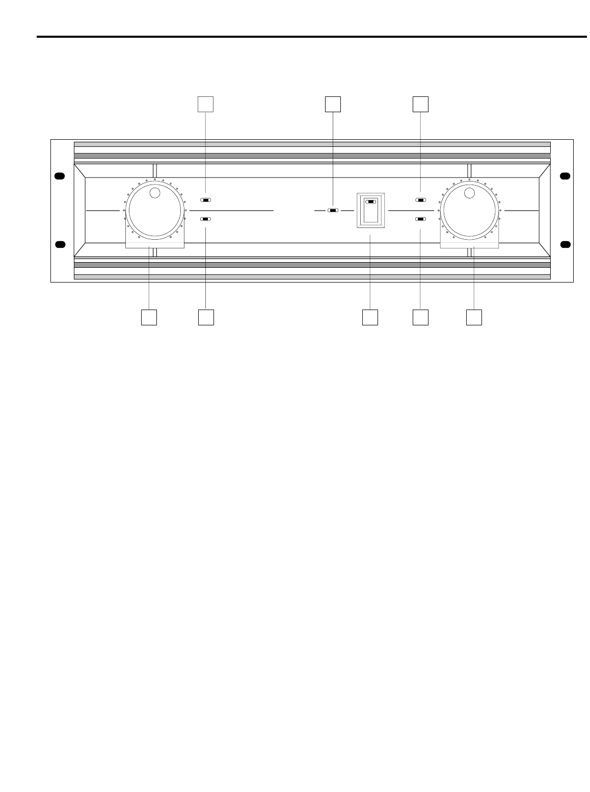
Guided Tour - Servo-550 Front Panel
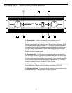
1: Power switch - Use this to power the Servo Amplifier on or off.
2: Channel input controls (left/right) - These 41-position knobs allow you to
adjust the input level of the signal arriving at the rear-panel input jacks. At the
fully counterclockwise position (labeled “∞”), the signal is infinitely attenuated
(completely off). At the fully clockwise position (labeled “MAX”), the signal is at
unity gain (that is, no attenuation). When 0 dBu of signal arrives at the input
jacks and the Channel Input controls are set to their “MAX” position, the Servo
Amplifier delivers full power output.
3: Protection light - This light goes on for approximately five seconds when-
ever the Servo Amplifier is powered on and fades slowly when the amp is pow-
ered off. When lit, 0 volts DC are provided to all connected speakers, thus mut-
ing them and preventing any “thump” from occurring. For a complete description
of the conditions under which this light goes on, see Appendix D (“The Servo
Amplifier Protection Circuitry”) on page 12 of this manual.
4: Clip lights (left/right) - These lights go on whenever the signal being input to
the corresponding channel rises to a distortion level above .03% THD.
5: Idle lights (left/right) - These lights go on whenever signal is present at the
corresponding input. They go off when no signal is present.
5
∞
MAX
∞
MAX
CLIP
IDLE
CLIP
IDLE
PROTECTION
SERVO - 550
STUDIO AMPLIFIER 275 WATT STEREO
POWER
SAMSON
4
52 1
3
4
5 2