36
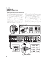
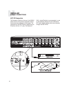
12VDC Page Trigger In
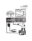
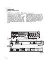
When 12VDC is applied to the Page Trigger In,
the system will page audio that is connected to
the Page Audio Input and interrupt the video out-
puts with the page video signal. The Page Trigger
In is located in the Page connection area of the
CAV6.6 Controller. The connections for the trig-
ger are made using a two-conductor cable with
1/8” male mini-plug jacks. The tip is positive (+)
and sleeve is negative (-). This allows for the con-
nection of an external paging or muting device
such as the Russound DIM-1 Doorbell Interface
Module. The CAV6.6 can be programmed to
mute audio and video for one or all zones as pre-
ferred when the 12VDC is applied.
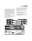
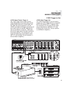
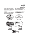
12VDC Page Trigger Out
Page Trigger Out 12VDC output is available
under several programmable situations, such as
for triggering an external amplifier, muting
device or other paging component dependent
on the Page Trigger In 12VDC. The connections
for the output are made using a two-conductor
cable with 1/8” male mini-plug jacks at each
end. The tip is positive (+) and sleeve is nega-
tive (-). The default setting for the Page Trigger
Out provides 12VDC whenever 12VDC is applied
to the Page Trigger In.
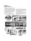
In some cases noise or interference may be
generated by external devices that are connected
to the 12 volt trigger outputs of the CAV. It may
be necessary to use a ferrite bead to reduce
this interference. Two to three turns of the con-
necting cable through the bead may be needed.
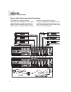
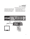
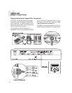
Page Audio/Video In
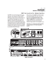
The Page Audio/Video Inputs accept line level
audio/video signals. The paging inputs interface
with the page output of a telephone, camera, or
other peripheral device. Connect the audio/video
signals using quality RCA cables.
INSTALLER
MAKING CONNECTIONS
12VDC Trigger In/Out


