


7
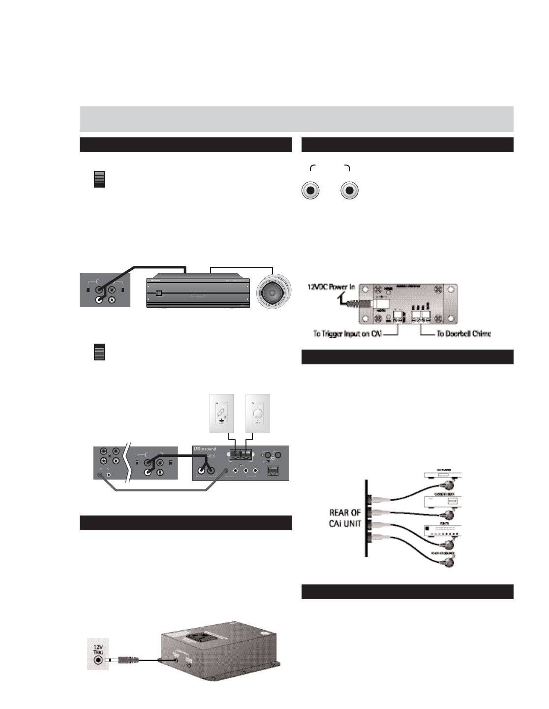
ZONE PRE-AMP OUTPUTS
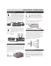
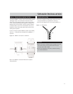
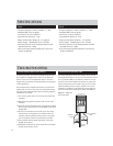
Switch in VARIABLE Position: In applications
where more power than the 20 watts per chan-
nel is desired, connect one or more zones of the
CAi to an external amplifier. Using standard
RCA connectors, wire from the pre-amp outputs of the CAi to
the amplifier's inputs. A typical application for more power is
when connecting an outside zone where the audio power
requirements would be much greater than an inside zone.
Figure 5a - Variable Output Connection
Switch in FIXED Position: When adding sub-
zones, connect an amplifier or A-BUS Hub to
the RCA connection. When the switch is in the
FIXED position, the audio level will not be var-
ied by the keypad volume for the zone.
Figure 5b - Fixed Output
Connection
12-VOLT TRIGGER OUTPUT
The 12 volt trigger is engaged when any of the zones are on
and disengaged when the last zone is turned off. The trigger
can be used to engage any 12 volt triggered accessory, such
as a triggered AC outlet or audio amplifier. The connection
for the trigger is made through an 1/8” male mini-plug jack.
The tip is (+) and sleeve is (-).
Figure 6 - 12-Volt Trigger Output Connection
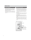
MUTE
When used with the optional Doorbell or
Telephone interface, the Mute Input
mutes the audio to the speakers, the
doorbell is used or when the telephone
rings. The connection for the Mute Input is made through a
1/8” male mini-plug. The tip is (+) and the sleeve is (-),
12VDC.
When more than one CAi is used, connect the MUTEOUT of
the first CAi to the MUTEIN of the second CAi.
Figure 7 - DIM-1 Doorbell Interface Module
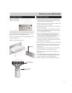
CONNECTING THE INFRARED COMPONENTS
•In order for your CAi to transmit the IR signal from the
keypads to a source, an emitter must be connected from
the IR outputs marked 1-4. All IR outputs are common
•Connect each 845.1 mini-emitter to the IR output.
•Remove the adhesive back and position the IR receiver on
the product you wish to control. Stick the 845.1 emitter
directly over the source components IR window.
Figure 8 - IR Emitter Connections
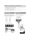
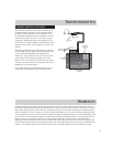
CONNECTING THE (IR) LINK
When two or more CAi Controllers are to be used in an
installation, the LINK connection is used to pass IR signal
between the two units. Use an 1/8” mini-plug, male-to-male
cable (included) connected from the LINK OUT on the first
CAi Controller to the LINK IN on the second CAi. When con-
nected, you may connect your IR emitters to either CAi unit’s
IR EMITTERS jacks.
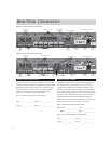
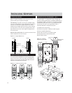
REAR PANEL CONNECTIONS
1
R
L
2
ZONE PREAMP
OUTPUTS
VARIABLE
FIXED
VARIABLE
FIXED
VARIABLE
FIXED
VARIABLE
FIXED
1234
L
IR E
MITTERS
IR
C
ONFIRM
DESIGNED IN USA MADE IN KOREA
P
OWER
24VDC 4A
S
TATUS
12VDC 100mA
NEWMARKET, NH U.S.A.
R
A-H2
2-Z
ONE, 1-SOURCE
SURFACE MOUNT AUDIO HUB
A
UDIO
I
N
12
K
EYPAD
O
UTPUTS
E
XPANSION
I
NPUT
B
YPASS
S
TATUS
1
R
L
2
ZONE PREAMP
OUTPUTS
VARIABLE
FIXED
VARIABLE
FIXED
R
L
LINK
IN OUT
Rear of CAi unit
IR Link Cable
IR Emitter Out
IR Link In
A-BUS Hub
MUTE
IN
OUT
ACT-1