15
The Russound CAi-Series Controllers are fully guaranteed for Two (2) years from the date of purchase against all defects in
materials and workmanship. During this period Russound will replace any defective parts and correct any defect in workman-
ship without charge for either parts or labor. For this warranty to apply, the unit must be installed and used according to its
written instructions. If service is necessary, it must be performed by Russound. The unit must be returned to Russound at the
owners expense and with prior written permission. Accidental damage and shipping damage are not considered defects under
the terms of the warranty. Russound assumes no responsibility for defects resulting from abuse or servicing performed by an
agency or person not specifically authorized in writing by Russound. Damage to or destruction of components due to
improper use voids the warranty. In these cases the repair will be made at the owners expense. To return for repairs, the unit
must be shipped to Russound at the owners expense, along with a note explaining the nature of the service required. Be sure
to pack in a corrugated container with at least 3 inches of resilient material to protect the unit from damage in transit.
TROUBLESHOOTING
WARRANTY
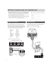
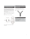
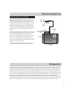
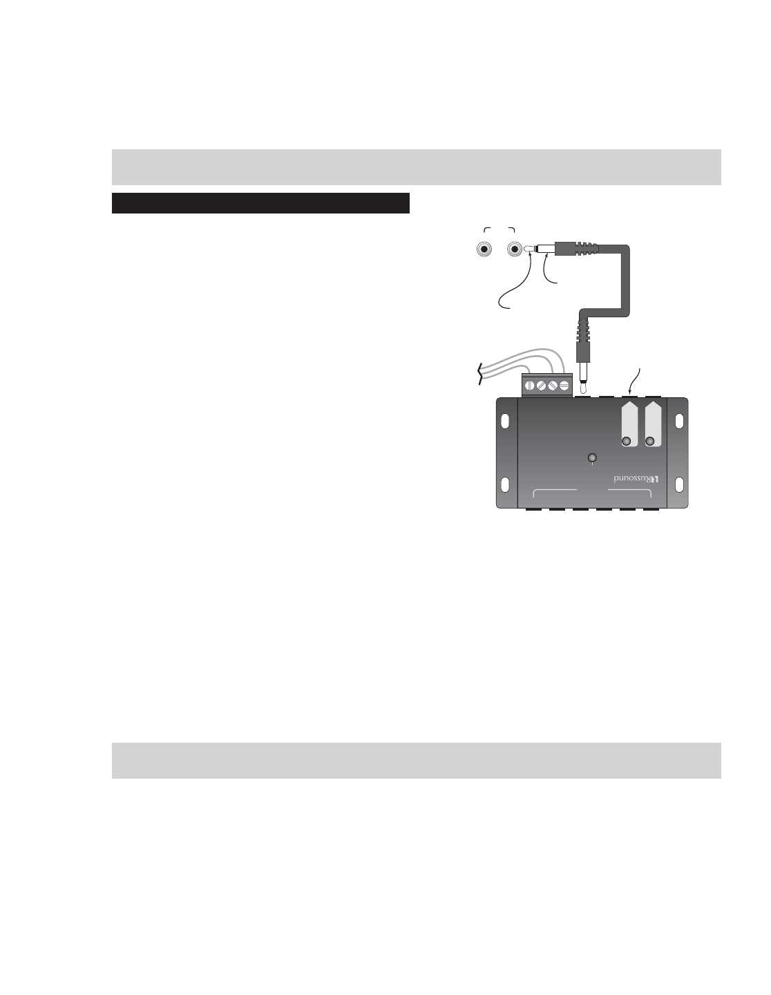
COMBINING ADDITIONAL IR RECEIVERS
When combining a CAi Series multi-source controller and a
secondary IR system together, it needs to be done after the
CAi System. The IR information from the keypad is on Pin
#2. This signal is demodulated at the keypad and is re-mod-
ulated at the processor then sent to the emitter out-puts.
Combining a modulated IR signal to this lead (#2) will not
work because it is already modulated. The following method
should be used to assure correct integration with such com-
ponents.
Simply plug the IR linking cable supplied with the CAi prod-
uct into the IR “Link Out” jack on the CAi and plug the other
end into the Russound 857 IR Connecting Block’s “IR
Common In”. The secondary IR receiver can either be wired
to the terminal block as shown or plugged into the “IR
Reciever In” via an 1/8” mini-plug. The emitters that would
have been connected directly to the CAi system will now be
plugged into the connecting block.
This method combines the modulated IR signal at the con-
necting block then distributes it to the six emitter ports.
LINK
IN OUT
845.1 MICRO EMITTERS
TO IR CONTROLLED
EQUIPMENT
GROUND
SIGNAL
TO SECOND
IR RECEIVER
CONNECT TO
846C POWER
SUPPLY
857
CONNECTING
BLOCK
123456
IR R
ECEIVER
I
N
IR C
OMMON
I
N
IR C
ONFIRM
+
12VDC
GND
STATUS
SIGNAL
E
MITTERS
S
TATUS
+
12VDC
P
OWER
+
12VDC
DESIGNED IN USA MADE IN KOREA
857 I
NFRARED
C
ONNECTING
B
LOCK


