


9
In normal operation, use the STANDBY switch
to deactivate the unit when you are finished
listening and leave the POWER switch ON
at all times. This will preserve memory func-
tions.
NOTE
: The STANDBY switch also controls
the rear panel AC outlets. When the RX-975
is in STANDBY mode, the AC outlet is also
off. When the RX-975 is fully functional, the
AC outlet is live.
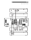
Remote Sensor
This sensor receives infrared signals from the
handheld remote control. Make sure you do
not accidentally block this sensor with cables
or accessories.
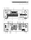
Front Panel Display
The large fluorescent display in the upper
portion of the RX-975 provides status infor-
mation used in operating the AM/FM re-
ceiver (such as station frequency display,
band, preset memory, etc.).
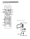
MASTER VOLUME
The MASTER VOLUME control adjusts the
level of all output channels simultaneously.
Rotate the control clockwise to increase the
volume. Rotate counterclockwise to decrease
the volume. MASTER VOLUME buttons are
also available on the RX-975's handheld re-
mote control.
When you adjust the volume, a bar indica-
tor in the display shows the volume setting.
TONE Controls
BASS and TREBLE controls increase and
decrease the audio signal’s low and high
frequency content respectively. Rotate clock-
wise to increase output in the respective fre-
quency range and counterclockwise to re-
duce it. The center detent removes each
control from the audio path for maximum
signal integrity.
BALANCE Control
Turn the BALANCE control clockwise to in-
crease the output level of the right channel
speakers. Turn counterclockwise to increase
the output level of the left channel speakers.
The center detent position removes the control
from the circuit and provides equal output
from both left and right channels.
HEADPHONES Jack
This jack accepts a standard 1/4 inch ste-
reo headphone plug. Use an adaptor if your
headphones have the smaller mini-plug.
Inserting a headphone plug will automati-
cally disable all speaker outputs.
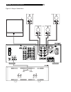
SPEAKER Button and
SPEAKER LEDs
The RX-975 provides output connections for
two pairs of speakers: A and B. The SPEAKER
BUTTON controls which pairs of speakers
outputs, if any, are active. A pair of SPEAKER
LED indicators located to the left of the DIS-
PLAY shows the current speaker selection.
Press the SPEAKER button repeatedly to step
sequentially through the four available
speaker options:
•
Speakers A active (LED A only lit)
•
Speakers B active (LED B only lit)
•
Speakers A and B active (both LEDs lit)
•
All speakers off (no LEDs lit)
NOTE
: Inserting a headphone plug into the
headphone jack disables all speaker out-
puts, regardless of the SPEAKER button set-
ting.
MEMORY Button
The MEMORY button is used to confirm and
memorize tuner station presets. Its use is
described in detail in the Tuning Controls sec-
tion of this manual.
Input Source Buttons
Ten large front panel buttons directly select
an audio or video input source (such as a
CD player, the built-in tuner, a tape recorder,
video sources, etc.) for listening. Push any
of these buttons (or the duplicates on the
handheld remote) to select the desired source.
You will hear this source and, if you have
selected a video source, see its picture on
your TV monitor. The front panel display will
show the current source selection.
TAPE MONITOR Buttons: Two of the IN-
PUT SOURCE buttons have a special func-
tion. The TAPE 1 and TAPE 2 MONITOR
buttons activate the audio inputs of a tape
monitor loop consisting of a pair of outputs
and a matching set of inputs. Normally, this
tape monitor loop is used to play a tape deck
connected to these inputs or for real time
monitoring of a recording in progress on an
audio tape deck. Alternatively, the tape
monitor loop could be used to pass a sig-
nal to a graphic equalizer and listen to the
processed signal by pressing the correspond-
ing TAPE MONITOR button. An indicator ap-
pears in the front panel display when TAPE
2 MONITOR is activated.
English