


13
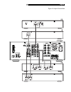
The back panel speaker connections con-
sist of two groups of binding posts which
accept bare wire or banana type plug con-
nectors (except in the European Community
countries where their use is not permitted).
One group is used for the A speakers; the
other for the B speakers. Each group has a
positive (+) and negative (–) connection for
the right speaker and a positive (+) and
negative (–) connection for the left speaker
Each pair of connectors is color-coded for
polarity: red for the positive connection and
black for the negative connection. All speak-
ers and all speaker wire is also marked for
polarity. It is essential for proper performance
to maintain this polarity at all speaker con-
nections. Always connect the positive terminal
of each speaker to the corresponding red
speaker terminal on the RX-975 and the
negative speaker terminal to the correspond-
ing black connector on the RX-975.
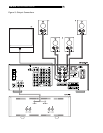
Route the wires from the RX-975 to the speak-
ers. Give yourself enough slack so you can
move the components to allow access to the
speaker connectors. If you are using banana
plugs, connect them to the wires and then
plug into the backs of the binding posts. The
collars of the binding posts should be screwed
in all the way (clockwise). If you are attaching
bare wires directly to the binding posts,
separate the wire conductors and strip back
the insulation from the end of each conduc-
tor. Be careful not to cut into the wire strands.
Unscrew the binding post collars. Insert the
wire into the hole in the shaft. Turn the col-
lars clockwise to clamp the wire in place.
NOTE
: Be sure there are no loose wire
strands that could touch adjacent wires or
connectors.
Preamp Inputs/Outputs
The RX-975 provides a pair of variable-level
RCA preamp audio outputs and a pair of
RCA amplifier inputs that allow you to use
external amplifiers in place of, or in addi-
tion to, the built-in amplifiers.
NOTE
: The preamp outputs are connected
to power amplifier inputs with metal jump-
ers in a standard PRE OUT/MAIN IN con-
figuration. To disable the built-in power
amplifiers and use external amplifiers, it will
be necessary to remove these jumpers. Save
them for future use.
To hook up the RCA audio outputs
to an external amplifier, connect a standard
audio cable from each output to the input
of the amplifier channel that will power the
corresponding speaker.
Antenna Connections
The RX-975 requires two antennas to receive
radio signals, one for AM and one for FM.
Most users will get acceptable reception using
the indoor antennas which are supplied with
the RX-975. Instructions for hooking up these
antennas follow.
NOTE
: If you are located a long distance
from the radio transmitters, you may use
an outdoor antenna to improve reception.
Outdoor antenna systems can be danger-
ous if they are not properly grounded and
should be installed by a professional con-
tractor familiar with the electrical code re-
quirements in your local area.
AM Loop Antenna
The RX-975 includes a loop antenna to re-
ceive AM radio signals. Remove this antenna
from the box and locate it near the RX-975.
Connect the 300 ohm twin-conductor wire
from the loop antenna to the pair of screw
terminals labeled AM LOOP, attaching one
wire to each terminal. It does not matter which
wire attaches to which terminal, but make
sure that the connections are solid and that
the two wires do not touch.
You may need to rotate or otherwise reori-
ent the antenna to find the best position.
NOTE
: To use an outdoor antenna, connect
its 300 ohm twin-conductor wire to the AM
terminals in place of the loop antenna, only
after a professional contractor has installed
the antenna system in accordance with lo-
cal electrical codes.
FM Wire Antenna
The RX-975 includes a wire antenna to re-
ceive FM signals. In many countries (including
the USA), this antenna is a T-shaped twin-
conductor 300 ohm antenna. Remove this
antenna from the box and connect its two
conductors to the two screw terminals on the
supplied 300 ohm to 75 ohm adaptor. Con-
nect the coax plug on the converter to the
FM 75 ohm antenna connector on the
RX-975.
For best reception, unfold the T-shaped wire
antenna. There are eyelets at both ends of
the T, which allow tacking the antenna to a
wall, if desired. Experiment with position-
ing for best reception.
In some countries, the RX-975 may be sup-
plied with a single wire FM antenna termi-
nated by a 75 ohm coax connector. If your
unit is supplied with this antenna, connect
it directly to the FM 75 ohm antenna con-
nector.
NOTE
: To use an outdoor antenna, connect
its 75 ohm coax lead wire (or 300 ohm
twin-conductor wire and 300 ohm to 75
ohm adaptor) to the FM 75 ohm connector
in place of the indoor wire antenna, only
after a professional contractor has installed
the antenna system in accordance with lo-
cal electrical codes.
English