


6
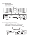
Input Signal Connections
See Figure 2
The RB-1050 has conventional RCA type in-
put connectors, the type found on nearly all
audio equipment.
NOTE: To prevent loud potentially damag-
ing noises, make sure the amplifier is
turned off when you make any changes to
the input signal configuration.
Select high quality audio interconnect cables.
Connect each of the outputs from the pream-
plifier or signal processor to the correspond-
ing input of the RB-1050. Typically the left
channel signal is connected to Channel 1 and
the right channel signal is connected to Chan-
nel 2.
Front Panel Level Controls
The Level controls on the front panel let you
control the output volume of the RB-1050. In
most systems these controls should be turned
up all the way (full clockwise position). In some
situations, such as when the amplifier is part
of a multi-room or bi-amplified speaker sys-
tem, it may be necessary to reduce the out-
put level. Use a small flat blade screwdriver
to turn the controls down (counterclockwise)
as needed.
Turning down the level does not reduce the
maximum output of the amplifier. It simply
increases the input signal required to achieve
maximum output power.
“Signal Output Link”
Connectors
The input signal that is goes into the normal
Inputs also goes to the Signal Output Link
connectors. This is typically used when the
amplifier is part of a multi-room system. The
signal from the Signal Output Link is then used
to provide a signal to the other amplifiers in
the system.
Speaker Connection
Speaker Selection
We recommend using loudspeakers with a
nominal impedance of 4 ohms or higher with
the RB-1050. You should exercise some cau-
tion in driving multiple pairs of speakers in
parallel configuration, because the effective
impedance the amplifier sees is cut in half.
For example, when driving two pair of 8 ohm
speakers, the amplifier sees a 4 ohm load.
When driving multiple speakers in parallel,
it is recommended that you select speakers
with a nominal impedance of 8 ohms or higher.
Speaker impedance ratings are less than
precise. In practice, very few loudspeakers will
present any problems for the RB-1050. See
your authorized Rotel dealer if you have any
questions.
Speaker Wire Selection
Use insulated two-conductor stranded wire to
connect the RB-1050 to the speakers. The size
and quality of the wire can have an audible
effect on the performance of the system. Stan-
dard speaker wire will work, but can result
in lower output or diminished bass response,
particularly over longer distances. In general,
heavier wire will improve the sound. For best
performance, you may want to consider spe-
cial high-quality speaker cables. Your autho-
rized Rotel dealer can help in the selection
of appropriate cables for your system.
Polarity and Phasing
The polarity — the positive/negative orien-
tation of the connections — for every speaker
and amplifier connection must be consistent
so all the speakers will be in phase. If the po-
larity of one connection is mistakenly reversed,
bass output will be very weak and stereo im-
aging degraded. All wire is marked so you
can identify the two conductors. There may
be ribs or a stripe on the insulation of one
conductor. The wire may have clear insula-
tion with different color conductors (copper
and silver). There may be polarity indications
printed on the insulation. Identify the positive
and negative conductors and be consistent with
every speaker and amplifier connection.
Speaker Connection
The RB-1050 has two pairs of color coded
binding posts on the back panel. These con-
nectors accept bare wire, connector lugs, or
dual banana type connectors (except in the
European Community countries where their
use is not permitted).
Route the wire from the RB-1050 to the speak-
ers. Give yourself enough slack so you can
move the components enough to allow access
to the speaker connectors.
If you are using dual banana plugs, connect
them to the wires and then plug into the backs
of the binding posts. The hexagonal thumb-
screws of the binding posts should be screwed
in all the way (clockwise).
If you are using terminal lugs, connect them
to the wires. If you are attaching bare wires
directly to the binding posts, separate the wire
conductors and strip back the insulation from
the end of each conductor. Be careful not to
cut into the wire strands. Unscrew (turn coun-
terclockwise) the binding post hexagonal
thumbscrews. Place the connector lug or wire
around the binding post shaft. Turn the hex-
agonal thumbscrews clockwise to clamp the
connector lug or wire firmly in place.
NOTE: Be sure there are no loose wire
strands that could touch adjacent wires or
connectors.
RB-1050 Stereo Power Amplifier