


4
About Rotel
A family whose passionate interest in music
led them to manufacture high fidelity compo-
nents of uncompromising quality founded Rotel
over 40 years ago. Through the years that
passion has remained undiminished and the
family goal of providing exceptional value for
audiophiles and music lovers, regardless of
their budget, is shared by all Rotel employ-
ees.
The engineers work as a close team, listen-
ing to, and fine tuning each new product until
it reaches their exacting musical standards.
They are free to choose components from
around the world in order to make that product
the best they can. You are likely to find ca-
pacitors from the United Kingdom and Ger-
many, semi conductors from Japan or the
United States, while toroidal power transform-
ers are manufactured in Rotel’s own factory.
Rotel’s reputation for excellence has been
earned through hundreds of good reviews and
awards from the most respected reviewers in
the industry, who listen to music every day.
Their comments keep the company true to its
goal – the pursuit of equipment that is musi-
cal, reliable and affordable.
All of us at Rotel thank you for buying this
product and hope it will bring you many hours
of enjoyment.
Getting Started
Thank you for purchasing the Rotel RB-1050
Stereo Power Amplifier. When used in a high-
quality music or home theater system, your
Rotel amplifier will provide years of musical
enjoyment.
The RB-1050 is a high-power, two-channel
power amplifier, providing the highest level
of audio performance. Discrete output devices,
a massive power supply, premium components,
and Rotel’s Balanced Design ensure superb
sound quality. High current capability allows
the RB-1050 to drive the most demanding loud-
speakers.
Be aware that the RB-1050 is capable of high
power levels, in excess of 70 watts per channel.
Make sure that your speakers can handle the
power of the RB-1050. If in doubt about your
speakers, ask your local Rotel audio dealer
for advice.
The RB-1050 is straightforward in its instal-
lation and operation. If you have experience
with other stereo power amplifiers, you
shouldn’t find anything perplexing. Plug in a
pair of high-quality RCA cables from your
preamp into the amplifier inputs, wire up your
speakers, and enjoy.
A Few Precautions
Please read this manual carefully. In addition
to basic installation and operating instructions,
it provides valuable information on various
RB-1050 system configurations as well as gen-
eral information that will help you get opti-
mum performance from your system. Please
contact your authorized Rotel dealer for an-
swers to any questions you might have. In ad-
dition, all of us at Rotel welcome your ques-
tions and comments.
Save the RB-1050 shipping carton and all en-
closed packing material for future use. Ship-
ping or moving the RB-1050 in anything other
than the original packing material may re-
sult in severe damage to your amplifier.
Fill out and send in the owner’s registration
card packed with the RB-1050. Also be sure
to keep the original sales receipt. It is your
best record of the date of purchase, which you
will need in the event warranty service is ever
required.
Placement
The RB-1050 generates heat as part of its nor-
mal operation. The heat sinks and ventilation
openings in the amplifier are designed to
dissipate this heat. The ventilation slots in the
top cover must be open. There should be 10
cm (4 inches) of clearance around the chas-
sis, and reasonable airflow through the in-
stallation location, to prevent the amplifier from
overheating.
Likewise, remember the weight of the ampli-
fier when you select an installation location.
Make sure that the shelf or cabinet can sup-
port its considerable bulk. Again, use com-
mon sense.
RB-1050 Stereo Power Amplifier
Contents
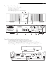
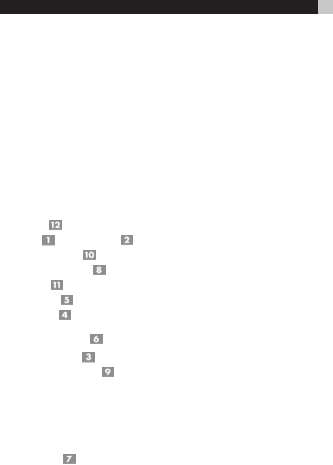
Figure 1: Controls and Connections 3
Figure 2: Preamp Input and Speaker
Output Connections 3
About Rotel .......................................... 4
Getting Started ..................................... 4
A Few Precautions 4
Placement 4
AC Power and Control ........................... 5
AC Power Input 5
Power Switch and Power Indicator 5
12V Trigger Mode Selector 5
12V Trigger Input and Output 5
Circuit Breakers 5
Protection Circuitry 5
Clipping Indicators 5
Input Signal Connections .................. 6
Front Panel Level Controls 6
“Signal Output Link” Connectors 6
Speaker Connection ............................... 6
Speaker Selection 6
Speaker Wire Selection 6
Polarity and Phasing 6
Speaker Connection 6
Troubleshooting ..................................... 7
Front Panel Power Indicator Is Not Lit 7
No Sound 7
Protection Indicator Is Lit 7
Specifications ........................................ 7