


6
RMB-1076 Six Channel Power Amplifier
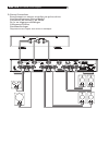
AC Power and Control
AC Power Input
-
The RMB-1076 is supplied with the proper AC
power cord. Use only this cord or an exact
equivalent. Do not use an extension cord. A
heavy duty multi-tap power outlet strip may
be used, but only if it is rated to handle the
current demand of the RMB-1076.
Be sure the Power Switch on the front panel of
the RMB-1076 is turned off. Then, plug one
end of the cord into the AC power connector
-
on the back panel of the amplifier. Plug the
other end into an appropriate AC outlet.
Your RMB-1076 is configured at the factory
for the proper AC line voltage in the country
where you purchased it (USA: 120 volts/
60 Hz, Europe: 230 volts/50 Hz). The AC
line configuration is noted on a label on the
back panel.
NOTE: Should you move your RMB-1076
to another country, it is possible to config
-
ure your amplifier for use on a different
line voltage. Do not attempt to perform this
conversion yourself. Opening the enclosure
of the RMB-1076 exposes you to danger-
ous voltages. Consult a qualified technician
or the Rotel factory service department for
information.
If you are going to be away from home for
an extended period of time, it is a sensible
precaution to unplug your amplifier.
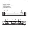
Power Switch and
Indicator
12
The Power Switch is located on the front panel.
To turn the amplifier on (or to activate either of
the optional automatic power-on modes), push
the switch in. The LED indicator above the switch
will light, indicating that the amplifier is turned
on. To turn the amplifier off, push the button
again and return it to the out position.
Auto Turn On/Off Mode
Selector
9
The RMB-1076 provides three options for
manual or automatic power on/off operation.
These modes are selectable using a three-posi
-
tion slide switch on the back panel:
• With the switch in the OFF position, the
amplifier is turned on or off manually us
-
ing the front panel power switch. Use this
mode if you are using a switched AC outlet
to control power to the amplifier.
• With the switch in the SIGNAL SENSING
position, the amplifier turns on automatically
when a signal is sensed at the inputs. The
amplifier will go into standby mode with
no signal. The front panel power switch
overrides this function. It must be ON for the
signal sensing to work. Turning the switch
OFF cuts power to the amplifier, regardless
of whether or not a signal is present.
• With the switch in the 12V TRIG. position,
the amplifier is turned on automatically
when a 12 volt trigger signal is applied to
the 3.5mm jack to the left of the switch. The
amplifier will go into standby mode with no
signal if the +12 volt signal is not present.
The front panel POWER SWITCH overrides
this function. It must be ON for the +12V
trigger to work. Turning the switch OFF cuts
power to the amplifier, regardless of whether
or not a trigger signal is present.
+12V Trigger Input
and Output
8
The jack labeled IN is for connecting the 3.5mm
Plug/Cable carrying a +12 volt trigger signal
to turn the amplifier on and off. To use this
feature the adjacent slide switch must be placed
to the left position (see previous section). This
input accepts any control signal (AC or DC)
ranging from 3 volts to 30 volts.
The jack labeled OUT is for connecting another
3.5mm plug/cable to provide a 12V trigger
signal to other components. The 12V output
signal is available whenever a +12 volt trigger
signal is applied to the IN connector.
Protection Indicator
3
Thermal and protection circuits protect the am-
plifier against potential damage in the event of
extreme or faulty operating conditions. Unlike
many designs, the RMB-1076’s protection cir
-
cuit is independent of the audio signal and has
no impact on sonic performance. Instead, the
protection circuit monitors the temperature of
the output devices and shuts down the amplifier
if safe limits are exceeded.
In addition, the RMB-1076 includes over-
current protection which operates only when
load impedances drop too low. This protection
is independent for each of the three pair of
channels and is indicated by the front panel
PROTECTION LED.
Should a faulty condition arise, the amplifier
channel at fault will stop playing and the PRO
-
TECTION LED on the front panel will light.
If this happens, turn the amplifier off, let it
cool down for several minutes, and attempt to
identify and correct the problem. When you
turn the amplifier back on, the protection circuit
will automatically reset and the PROTECTION
LED should go out.
In most cases, the protection circuitry activates
because of a fault condition such as shorted
speaker wires, or inadequate ventilation
leading to an overheating condition. In very
rare cases, highly reactive or extremely low
impedance speaker loads could cause the
protection circuit to engage.
Stereo Mode Selection
It is useful to think of the RMB-1076 as three
stereo amplifiers in a single chassis.
• Stereo mode: Conventional 2-channel stereo
operation for a pair of amplifier channels.
Minimum speaker load: 4 ohms.
Input Select Switches
6
A rear panel switch adjacent to the inputs can
select LINK to be On or Off for the first pair
of amplifier channels.
For Stereo mode: Slide the switch as
-
sociated with the desired pair of amplifier
channels to the right or OFF position. Use
both LEFT and RIGHT input connectors, and
connect one speaker to each pair of speaker
connectors.
NOTE: For groups “B” and/or “C”, you
can also place the INPUT SELECT switch
to the ON position for Stereo mode. This
routes the input signals from the “A” group