


7
AC Power and Control
AC Power Input
14
The RC-972 does not use a significant amount of power. However
there are two auxiliary power outlets on the back of the unit,
which can be used to supply power for other units. Consequently
it is usually best to plug the RC-972 directly into a 2-pin polarized
wall outlet. Avoid the use of extension cords. A heavy duty multi-
tap power outlet strip may be used if it (and the wall outlet) is
rated to handle the current demanded by the components
connected to it.
Note: Do not connect the power cord for a power amplifier to the
auxiliary power outlets on the RC-972. Power amplifiers often
draw more power than these outlets can provide.
Your RC-972 is configured at the factory for the proper AC line
voltage in the country where you purchased it (either 115 volts AC
or 230 volts AC with a line frequency of either 50 Hz or 60 Hz). The
AC line configuration is noted on a decal on the back panel.
Note: Should you move your RC-972 amplifier to another country, it
is possible to reconfigure your amplifier for use on a different line
voltage. Do not attempt to perform this conversion yourself. Open-
ing the enclosure of the RC-972 exposes you to dangerous volt-
ages. Consult a qualified service person or the Rotel factory
service department for information.
If you are going to be away from home for an extended period of
time such as a month-long vacation, it is a sensible precaution to
unplug your amplifier (as well as other audio and video
components) while you are away.
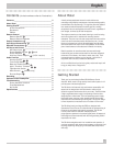
Power/Standby Switch
2
15
and
Power Indicator
1
The Power Indicator light above the Standby button is always
illuminated when the RC-972 is connected to a “live” AC outlet.
When the Power/Standby switch is pressed the RC-972 is turned
on. The Function indicator light and Volume Control indicator
light will illuminate. Pressing the Standby switch again will put
the RC-972 in “standby” mode and these indicator lights are
turned off.
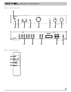
Auxiliary Power Outputs
13
(U.S.A. version)
The RC-972 has two switched outlets on the back panel. Power is
available from these outlets when the RC-972 is turned on. These
outlets can provide up to a total of 400 watts. They are appropriate
for supplying power to signal sources, such as CD players, tuners,
or tape decks. They should not be used for power amplifiers.
Connecting components that will draw more than 400 watts to
these outputs could damage the Standby switch in the RC-972.
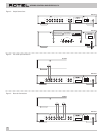
Input Signal Connections
10
[See Figure 4 for input connection illustration.]
The RC-972 has conventional RCA type input connectors, the type
found on nearly all audio equipment.
Note: To prevent loud noises that neither you nor your speakers
will appreciate, make sure the system is turned off when you
make any signal connections.
The CD, Tuner, and Aux inputs of the RC-972 are “line level”
inputs. These are for connecting components such as CD players,
Hi Fi or NICAM Stereo video cassette recorders, tuners for audio
or video, Laser Disc players or the analog output from a CD ROM
drive.
The Left and Right channels are clearly labeled and should be
connected to the corresponding channels of the source
component. The Left RCA connectors are white, the Right
connectors are red. Use high quality RCA cables for connecting
input source components to the RC-972. Ask your authorized Rotel
dealer for advice about cables.
Note: The optional phono board card enables you to connect a
phonograph to the RC-972. See your authorized Rotel dealer for
more information.
Recorder Connections
11
[See Figure 5 for recorder connection illustration.]
The Tape inputs and outputs can be connected to any record/
playback device that accepts standard line level analog input and
output signals. Typically that will be a conventional tape recorder.
When connecting a recorder to the RC-972 remember that the
outputs
of the recorder must be connected to the tape
inputs
of
the RC-972. Similarly the tape
outputs
of the RC-972 must be
connected to the
inputs
of the recorder. As with other sources be
sure to connect the Left and Right channels of each device to the
proper channels on the associated components. Use high quality
connecting cables to prevent loss of sound quality.
English