


W
IRING
T
HE
S
YSTEM
CAUTION: Avoid running power wires near the low level input cables, antenna, power leads, sensitive equipment or
harnesses. The power wires carry substantial current and could induce noise into the audio system.
1. Configure the internal XCard crossovers prior to installation. Refer to the “Using the Signal Switching Network” (page
19 for the 50.2 and page 31 for 50.1) for further information.
2. Plan the wire routing. Take care when running signal level RCA cables to keep them close together but isolated from
the amplifier's power cables and any high power auto accessories, especially electric motors. This is done to prevent
coupling the noise from radiated electrical fields into the audio signal. When feeding the wires through the firewall or
any metal barrier, protect them with plastic or rubber grommets to prevent short circuits. Leave the wires long at this
point to adjust for a precise fit at a later time.
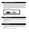
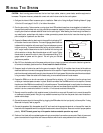
3. Prepare the Power cable for attachment to the amplifier by stripping 5/8"
of insulation from the end of the wire. The use of 8 gauge power cable can
interfere with the installation of the end caps. Proper wire dress can prevent
this from occurring. To prevent the wire from fraying, strip the insulation at
a 45° angle. Insert the bared wire into the B+ terminal with the long side
of the insulation on the top. Bend the cable down at a 90° angle. Tighten
the set screw to secure the cable in place. We recommend using (2) 8
gauge cables for power and for ground. This will give you the best
performance possible.
4. Strip 3/8" from the battery end of the power cable and crimp a large ring terminal to the cable. Use the ring terminal
to connect to the battery positive terminal. Do not install the fuse at this time.
5. Prepare a length of cable to be used for the ground connection. Strip 5/8" of insulation from the end of the cable as
described above and connect to the appropriate terminal of the amplifier. Prepare the chassis ground by scraping any
paint from the metal surface and thoroughly clean the area of all dirt and grease. Strip the other end of the wire and attach
a ring connector. Fasten the cable to the chassis using a non-anodized screw and a star washer.
6. Prepare the REM turn-on wire for connection to the amplifier by stripping 1/4" of insulation from the wire end and
crimping an insulated spade connector in place. Slide the connector over the REM terminal on the amplifier. Connect
the other end of the REM wire to a switched 12 volt positive source. The switched signal is usually taken from the source
unit's auto antenna or the accessory lead. If the source unit does not have these outputs available, the recommended
solution is to wire a mechanical switch in line with a 12 volt source to activate the amplifier.
7. Securely mount the amplifier (with supplied screws) to the vehicle or amp rack. Be careful not to mount the amplifier
on cardboard or plastic panels. Doing so may enable the screws to pull out from the panel due to road vibrations or
sudden vehicle stops.
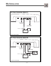
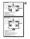
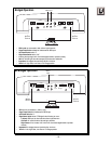
8. Connect the source signal to the amplifier by plugging the RCA cables into the input jack(s) at the amplifier. If using
Balanced Line Inputs, refer to page 24.
9. Connect the speakers. Strip the speaker wires 5/8" and insert into the appropriate terminal on the amplifier. Insert the
bared wire into the speaker terminal and tighten the set screw to secure into place. Be sure to maintain proper speaker
polarity.
DO NOT chassis ground any of the speaker leads as unstable operation may result.
10. Perform a final check of the completed system wiring to ensure that all connections are accurate. Check all power and
ground connections for frayed wires and loose connections which could cause problems from road vibrations.
– 11 –
><
5/8"
INSULATION
STRIP WIRE
>
>
AMP
>