


6
INSTALLA
TION
WIRING THE SYSTEM
CAUTION: If you do not feel comfortable with wiring your new unit, please see
your local Authorized Rockford Fosgate Dealer for installation.
CAUTION: Before installation, disconnect the battery negative (-) terminal to
prevent damage to the unit, fire and/or possible injury.
CAUTION: Avoid running power wires near the low level input cables, antenna,
power leads, sensitive equipment or harnesses. The power wires carry
substantial current and could induce noise into the audio system.
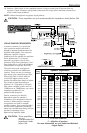
1. Plan the wire routing. Keep RCA cables close together but isolated from the amplifier's power
cables and any high power auto accessories, especially electric motors. This is done to prevent
coupling the noise from radiated electrical fields into the audio signal. When feeding the wires
through the firewall or any metal barrier, protect them with plastic or rubber grommets to
prevent short circuits. Leave the wires long at this point to adjust for a precise fit at a later time.
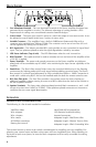
2. Prepare the RED wire (power cable) for attachment to the amplifier by stripping 1/2" of
insulation from the end of the wire. Insert the bared wire into the B+ terminal and tighten the set
screw to secure the cable in place.
NOTE: The B+ cable MUST be fused 18" or less from the vehicle's battery. Install the fuseholder under
the hood and prepare the cable ends as stated above. Connections should be water tight.
3. Trim the RED wire (power cable) within 18" of the battery and strip 1/2"of insulation from the
end of the wire. Cut the wire loop that is attached to the fuseholder in half and splice the fuse
into the power line using appropriate inline connectors. Use the section of cable that was
trimmed earlier and connect it to the other end of the fuseholder.
4. Strip 1/2" from the battery end of the power cable and crimp a large ring terminal to the cable.
Use the ring terminal to connect to the battery positive terminal.
DO NOT install the fuse at
this time.
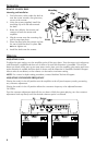
5. Prepare the BLACK wire (Ground cable) for attachment to the amplifier by stripping 1/2" of
insulation from the end of the wire. Insert the bared wire into the GND terminal and tighten the
set screw to secure the cable in place. Prepare the chassis ground by scraping any paint from
the metal surface and thoroughly clean the area of all dirt and grease. Strip the other end of the
wire and attach a ring connector. Fasten the cable to the chassis using a non-anodized screw
and a star washer.
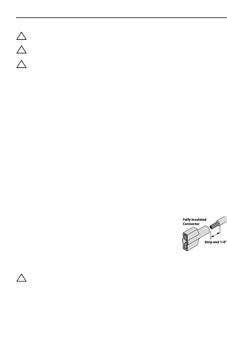
6. Prepare the REM turn-on wire for connection to the amplifier by
stripping 1/4" of insulation from the wire end. Using the fully insulated
connector provided, crimp the wire into the connector. Insure the
insulation on the wire is covered by the insulated connector and no
bare wire is visible. Slip the connector over the REM terminal on the
amplifier. Connect the other end of the REM wire to a switched 12 volt
positive source. The switched voltage is usually taken from the source
unit's accessory lead. If the source unit does not have this output
available, the recommended solution is to wire a mechanical switch in line with a 12 volt
source to activate the amplifier.
CAUTION: To prevent damage to the unit and/or personal property, only use a fully
insulated connector when connecting to the REM terminal. The
connector supplied is only for use with 14-18 gauge wire.
7. Securely mount the amplifier to the vehicle or amp rack. Be careful not to mount the amplifier
on cardboard or plastic panels. Doing so may enable the screws to pull out from the panel due
to road vibration or sudden vehicle stops.
8. Connect the source signal to the amplifier by plugging the RCA cables/high level inputs into the
input jacks at the amplifier.
9. Connect the speakers. Strip the speaker wires 1/2" and insert into the speaker terminal and
tighten the set screw to secure into place. Be sure to maintain proper speaker polarity. DO NOT
chassis ground any of the speaker leads as unstable operation may result.
!
!
!
!